
Hot continuous rolling mill finish rolling inlet variable speed control method

A technology of hot continuous rolling mill and control method, which is applied in the direction of rolling mill control device, metal rolling, metal rolling, etc., can solve unsolved problems, achieve the effect of reducing temperature control accuracy requirements, maximizing satisfaction, and improving temperature drop

Active Publication Date: 2014-07-23
BAOSHAN IRON & STEEL CO LTD
View PDF8 Cites 10 Cited by
  • Summary
  • Abstract
  • Description
  • Claims
  • Application Information

AI Technical Summary

Problems solved by technology

The method of this invention solves the problem that the flying shears adapt to different strip speeds, but does not solve how to dynamically correct the strip deceleration point according to the rolling type of the hot tandem rolling mill, and reasonably control the entrance speed of the rolling mill, thereby improving the overall rolling speed of the hot tandem rolling mill production line. The problem of production efficiency

Method used


Image

  • Hot continuous rolling mill finish rolling inlet variable speed control method
  • Hot continuous rolling mill finish rolling inlet variable speed control method
  • Hot continuous rolling mill finish rolling inlet variable speed control method

Examples


Embodiment Construction

[0054] In order to better understand the above technical solutions of the present invention, a further detailed description will be given below in conjunction with the drawings and embodiments.

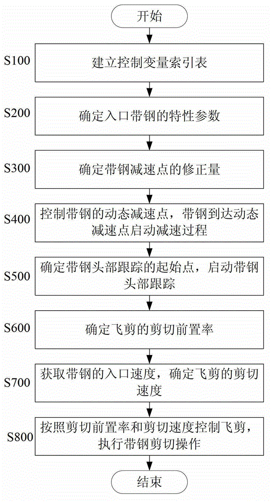
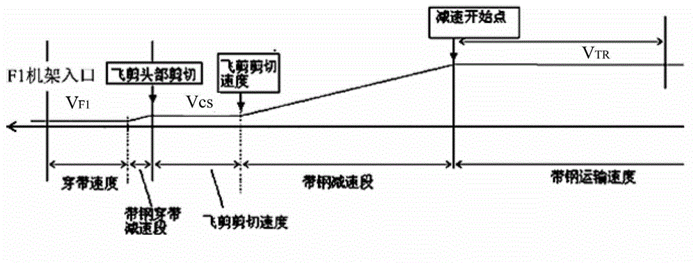
[0055] figure 1 It is a control flow diagram of an embodiment of the method for controlling the variable speed at the entrance of the hot rolling mill finish rolling of the present invention. The control method of the present invention is used in the flying shear shear speed control software of the continuous rolling mill during the hot rolling process. The described Flying shears are placed in front of the F1 stand at the entrance of the finishing rolling of the hot tandem rolling mill. The incoming strip passes through the deceleration point and enters the deceleration section, decelerates to the shearing speed of the flying sword, and is sent to the F1 stand after being cut by the flying shears. In the field of hot rolling, the definitions of steel grades by different manufacturer...


PUM


Abstract

The invention provides a hot continuous rolling mill finish rolling inlet variable speed control method which is especially suitable for metal rolling mills or control devices for machining products, and particularly relates to a method for controlling entrance speed of finish rolling strip steel of a hot continuous rolling mill through computer programs. According to four sets of compensation factors, feature parameters of the entering strip steel are determined; according to the feature parameters of the strip steel, speed reducing point correction of the strip steel is determined; according to the speed reducing point correction, a target speed reducing point of the strip steel is determined, and a dynamic speed reducing point is controlled; according to the target speed reducing point of the strip steel, a tracking start point of the head of the strip steel is determined; according to the feature parameters of the strip steel, the shear front-arranging rate of a flying shear is determined; according to the entrance speed of the strip steel and the shear front-arranging rate of the flying shear, the shearing speed of the flying shear is determined. Speed change points are determined according to the types and specifications of steel, the speed of the strip steel before flying shear is controlled in a multilevel mode, conveying time of the strip steel in an intermediate roller way is saved, the rolling efficiency of different strip steel can be maximized, and the rolling efficiency of the strip steel in the hot rolling process is improved.

Description

technical field [0001] The invention relates to a control device or method specially suitable for a metal rolling mill or its processed products, in particular to a method for controlling the inlet speed of a hot strip mill by using a computer program. Background technique [0002] As a hot rolling mill, the speed at which the strip enters the flying shear (disc shear) is directly related to the efficiency of hot rolling production, but because it involves the strip shear control process, the control of the strip running speed will directly affect As far as the control of the strip shear is concerned, once the shearing of the flying shear is affected, it will affect the control of the strip yield. For this reason, in the prior art, for the control of the shear velocity Vcs involved in the prior art, the shear velocity Vcs of flying shears generally adopts a fixed speed control method, such as figure 2 shown. Due to the entry speed V of the finish rolling F1 stand F1 It is...

Claims


Application Information

Patent Timeline
IPC IPC(8): B21B37/00B21B15/00
Inventor 荣鸿伟周兴泽王启尧
Owner BAOSHAN IRON & STEEL CO LTD
Learn More