
A wire head positioning and welding structure of a winding machine

A welding structure and winding machine technology, applied in welding equipment, auxiliary welding equipment, welding/cutting auxiliary equipment, etc., can solve the problems of troublesome wire grabbing and complicated positioning, and achieve the effect of high work efficiency and precision

Inactive Publication Date: 2017-01-18
GAOYIDA SCI & TECH SHENZHEN
View PDF5 Cites 0 Cited by
  • Summary
  • Abstract
  • Description
  • Claims
  • Application Information

AI Technical Summary

Problems solved by technology

In this case, on the one hand, it is more troublesome to grab the thread end when working with machinery, and on the other hand, the positioning is also more complicated.

Method used


Image

  • A wire head positioning and welding structure of a winding machine
  • A wire head positioning and welding structure of a winding machine
  • A wire head positioning and welding structure of a winding machine

Examples


Embodiment Construction

[0020] In order to further illustrate the technical means adopted by the present invention and its effects, the following describes in detail in conjunction with preferred embodiments of the present invention and accompanying drawings.

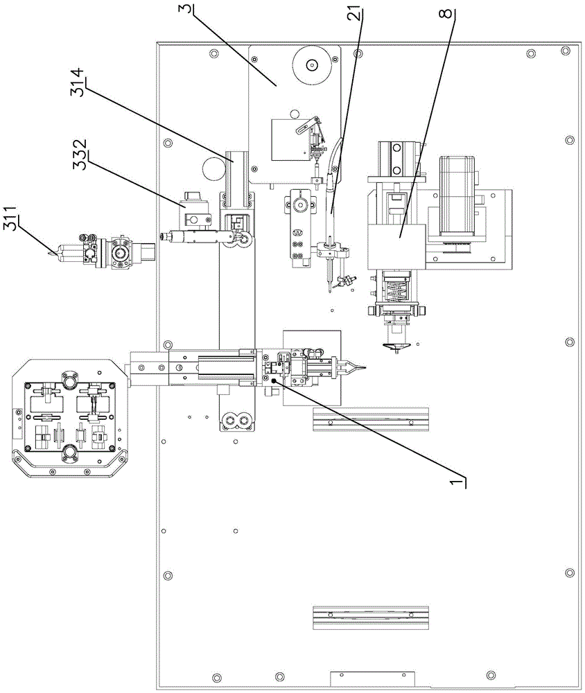
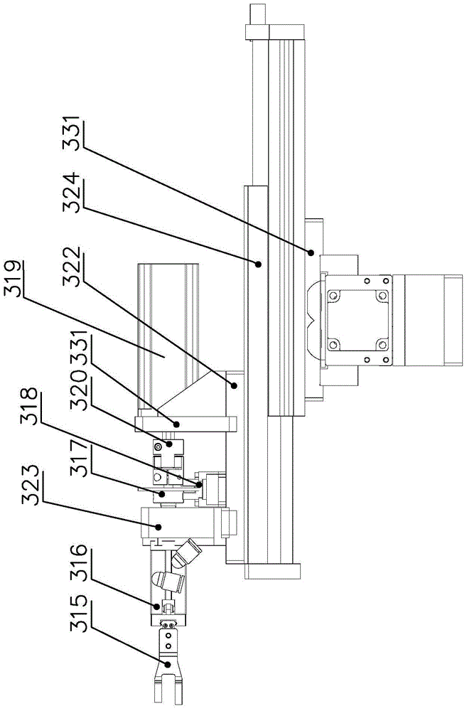
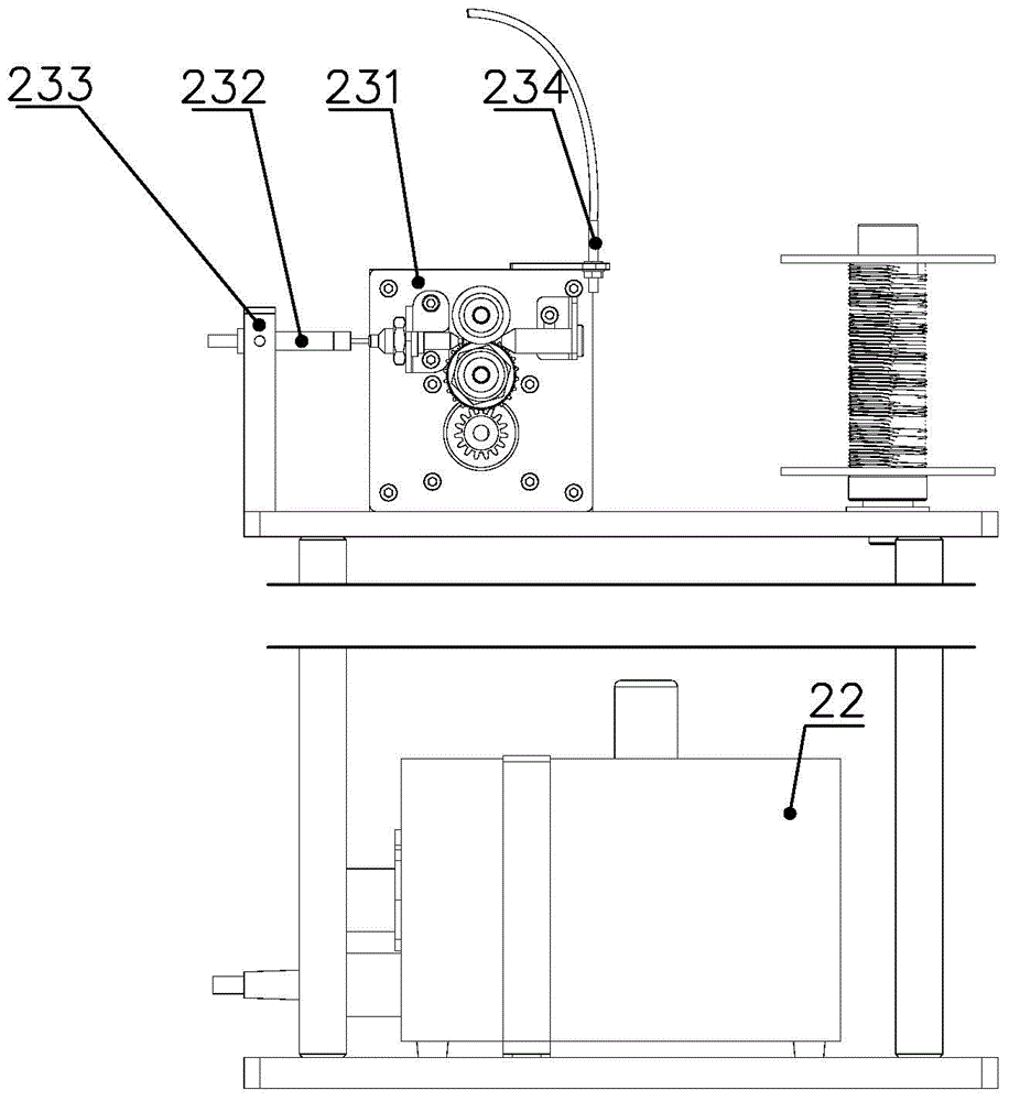
[0021] see Figure 1 to Figure 4 , in order to achieve the above object, the present invention provides a wire end positioning and welding structure, the wire end positioning structure 1 and the welding structure 2 are fixed on the winding machine, wherein the winding machine includes grabbing raw materials from the assembly line Mechanical arm 31, and thread cutting structure 33.

[0022] The mechanical arm 31 of the winding machine is mainly used for grabbing raw materials from the assembly line and intermediate products processed on the winding machine. The mechanical arm 31 can also cooperate with other mechanisms to fix the PCB board with the winding structure 3 .

[0023] The wire cutting structure 32 includes a support structure 331 an...


PUM


Abstract

The invention provides a winding machine wire head positioning and welding structure. The winding machine comprises a mechanical arm and a wire shearing structure, wherein the mechanical arm is used for grabbing raw materials from an assembly line. The wire head positioning structure comprises a clamping jaw and a plate conveying structure, the clamping jaw is arranged on the mechanical arm, and the plate conveying structure is arranged on a work platform. The plate conveying structure comprises a single shaft and clamping fingers, wherein the single shaft is arranged on a supporting plate, and the clamping fingers are perpendicular to the single shaft. The welding structure comprises a soldering iron controller and a tin conveying structure, the soldering iron controller controls soldering iron, the tin conveying structure comprises a guiding pipe connected with a wire conveying device, a wire conveying needle head connected with the guiding pipe, and an induction switch connected to the wire conveying device. By means of the wire head positioning and welding structure, a coil wire head can be automatically and rapidly positioned and fixed, and the coil wire head is welded to a specific welding spot of a PCB. The winding machine wire head positioning and welding structure is high in work efficiency and precision.

Description

technical field [0001] The invention relates to a wire head positioning and welding structure of a winding machine. Background technique [0002] For the welding of circuit boards with wound coils, manual operations are currently used, mainly because the wire ends of the welding coils are relatively small in size and short, and the welding points are fixed simultaneously. Like this, when working mechanically, it is cumbersome to grab the end of the thread on the one hand, and the positioning is also more complicated on the other hand. [0003] The present invention overcomes the above technical difficulties and develops a mechanical structure for automatic thread positioning and welding. Contents of the invention [0004] The object of the present invention is to provide an automatic winding machine wire head positioning and welding structure that does not require manual operation. [0005] In order to achieve the above purpose, the present invention provides a wire head...

Claims


Application Information

Patent Timeline
Patent Type & Authority Patents(China)
IPC IPC(8): B23K3/00B23K3/06B23K3/08B23K37/04
CPCB23K3/00B23K3/063B23K3/08B23K3/087
Inventor 王程明杨洪武
Owner GAOYIDA SCI & TECH SHENZHEN
Learn More