Shield structure for wire harness

a shield structure and wire harness technology, applied in the direction of insulated conductors, cables, coupling device connections, etc., can solve the problems of inability to perform the operation efficiently, no measure for defining the tightening position (crimping position) of the crimping tool relative to the shield pipe, etc., and achieve the effect of increasing the working efficiency

Active Publication Date: 2016-05-12
SUMITOMO WIRING SYST LTD
View PDF8 Cites 19 Cited by
  • Summary
  • Abstract
  • Description
  • Claims
  • Application Information

AI Technical Summary

Benefits of technology

[0007]The present invention was made based on circumstances such as those described above, and it is an object thereof to provide a shield structure for a wire harness that makes it possible to easily determine a tightening position of a crimp member relative to a shield pipe.
[0009]According to the present invention, the wire harness is surrounded by the shield pipe and the flexible shield member and is kept in a shielded state. Moreover, since the end surface of the shield pipe is covered by the end member, even if the end edge of the shield pipe is a sharp edge, the occurrence of a situation in which a coating of the conductive wire is damaged can be avoided. Moreover, since the end member is attached in such a manner as to cover the end edge of the shield pipe, the position of the end member relative to the shield pipe is fixed, and since the crimp member is disposed in the positioning portion that is formed in the end member, the tightening position of the crimp member relative to the shield pipe can be determined automatically. Thus, the working efficiency can be increased.

Problems solved by technology

However, in the above-described structure, no measure for defining the tightening position (crimping position) of a crimping tool relative to the shield pipe is taken.
Therefore, conventionally, the tightening position of the crimping tool is determined after manually measuring the distance from an end edge of the shield pipe, and thus it is not possible to perform the operation efficiently.

Method used


Image

  • Shield structure for wire harness
  • Shield structure for wire harness
  • Shield structure for wire harness

Examples


embodiment 1

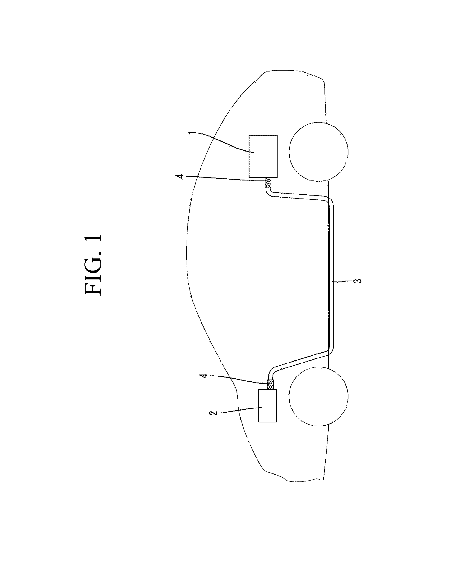
[0022]A shield structure for a wire harness of Embodiment 1 is applied to a hybrid vehicle.

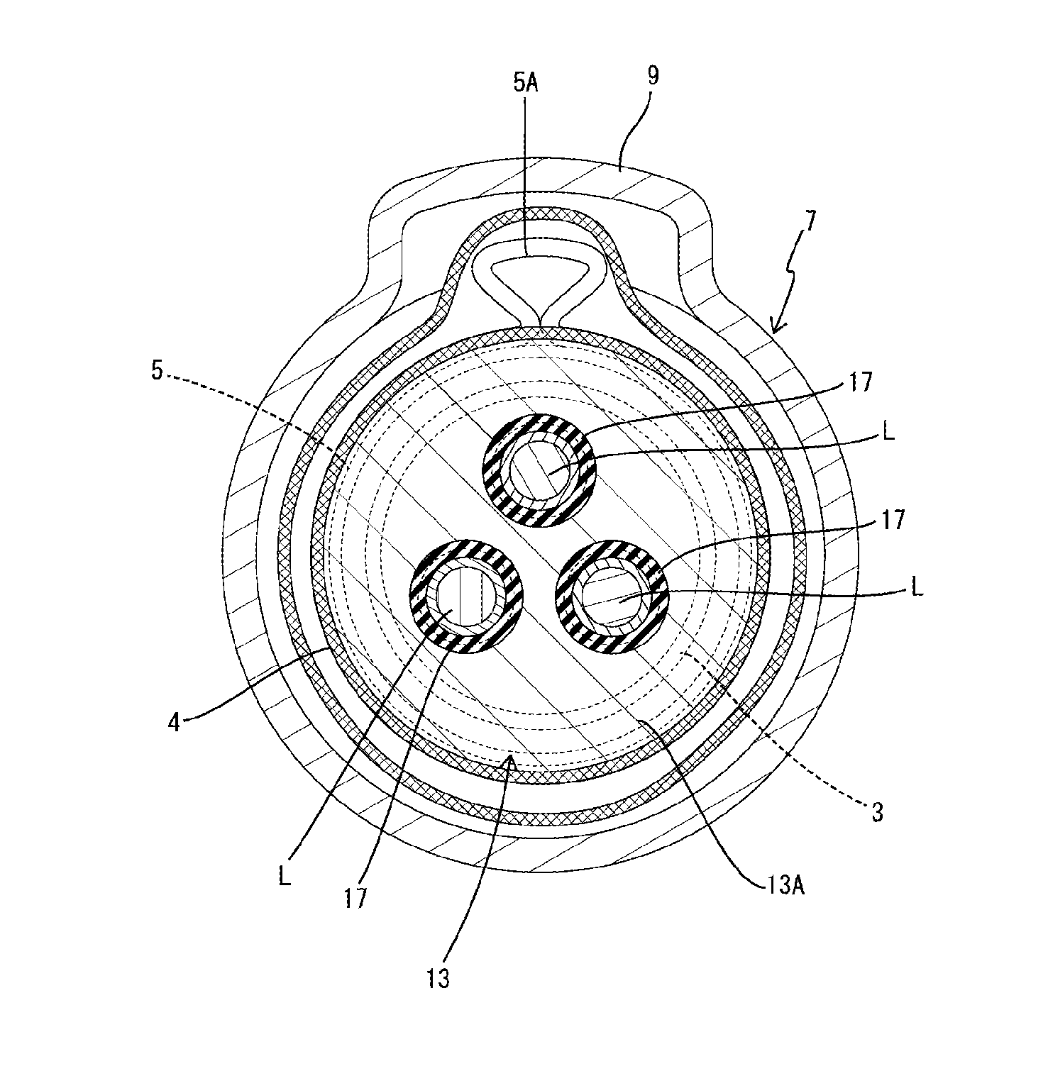
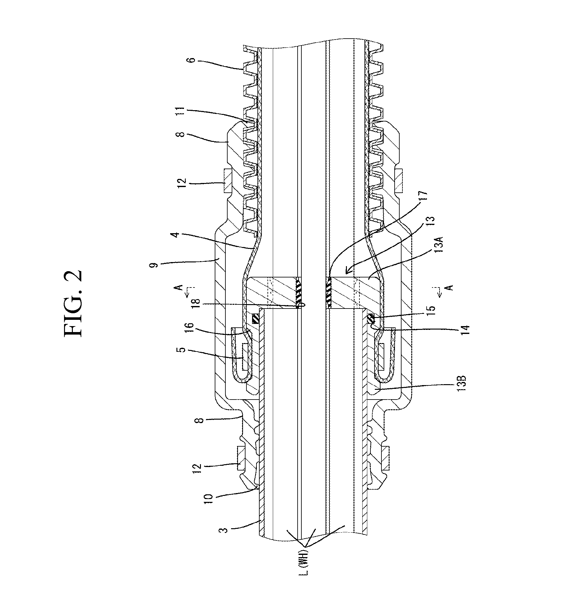
[0023]A wire harness WH connects a battery 1 that is installed on a rear side of the vehicle and an inverter 2 that is provided in an engine compartment to each other. In the case of the present embodiment, as shown in FIG. 2, the wire harness WH is constituted by three flexible conductive wires L.

[0024]An intermediate portion of the wire harness WH is collectively inserted in a shield pipe 3 that is disposed in an under-floor area of the vehicle. The shield pipe 3 is made of aluminum or an aluminum alloy and is composed of an elongated pipe having a circular cross-sectional shape. The shield pipe 3 is bent to be routed along a predetermined pipe arrangement route. The shield pipe 3 generally extends horizontally in a substantially front-rear direction of the vehicle. A front end side of the shield pipe 3 is bent upward to be introduced into the engine compartment, and a rear end side thereof ...


PUM


Abstract

A connecting position of a braid portion relative to a shield pipe is stabilized. A shield pipe in which a conductive wire constituting a wire harness is inserted, a braid portion that is connected to an end portion of the shield pipe and in which the conductive wire that is extended out of the shield pipe is inserted, an end member that is formed of a conductive material and that is mounted to an outer circumferential surface of the shield pipe while covering an end surface of the shield pipe, the braid portion being connected to an outer circumferential surface of the end member, and a crimp ring that crimps the braid portion onto the end member are provided. A positioning groove for positioning the crimp ring in an axial direction is formed on the outer circumferential surface of the end member.

Description

TECHNICAL FIELD[0001]The present invention relates to a shield structure for a wire harness.BACKGROUND ART[0002]Conventionally, in hybrid vehicles or electric automobiles, there are cases where a wire harness constituted by a plurality of wires is routed between a battery and an inverter in a state in which the wire harness is inserted in a metal shield pipe. An example of such a wire harness is disclosed in JP 2007-287335A.[0003]The aforementioned wire harness is inserted in a shield pipe that is routed along an under-floor area of a vehicle. On the other hand, in a portion of the wires that is led out of the shield pipe, that is, in a region where the wires are routed toward the battery or the inverter, the wires are inserted in a metal braid portion, which serves as a flexible shielding member, so that the routing direction can be adjusted freely.[0004]JP 2007-287335A is an example of related art.[0005]In the above-described structure, the metal braid portion is connected to the ...

Claims


Application Information

Patent Timeline
Patent Type & Authority Applications(United States)
IPC IPC(8): H02G3/04B60R16/02
CPCB60R16/0215H02G3/0462H01B7/17H01R4/06H01R13/5208H01R13/648H01R2201/26H02G3/0481H05K9/0098
Inventor KUSHIMA, TAKAO
Owner SUMITOMO WIRING SYST LTD
Why Eureka
Try Eureka