Automobile torsion beam suspension frame

A technology of torsion beam and suspension, applied in the direction of suspension, vehicle components, interconnection system, etc., can solve the problems of poor continuity of torsion beam suspension, high cost, affecting ride comfort and controllability, etc., and reduce cracking. Effects of risk, stress reduction, ease of installation and maintenance

Active Publication Date: 2014-07-23
CHERY AUTOMOBILE CO LTD
View PDF6 Cites 7 Cited by
  • Summary
  • Abstract
  • Description
  • Claims
  • Application Information

AI Technical Summary

Problems solved by technology

In addition, once the existing torsion beam suspension is put into production, its anti-roll resistance can only be adjusted by changing the spring hardness, which will inevitably affect ride comfort and handling
Moreover, different models have different requirements for handling and stability

Method used


Image

  • Automobile torsion beam suspension frame
  • Automobile torsion beam suspension frame
  • Automobile torsion beam suspension frame

Examples


Example Embodiment

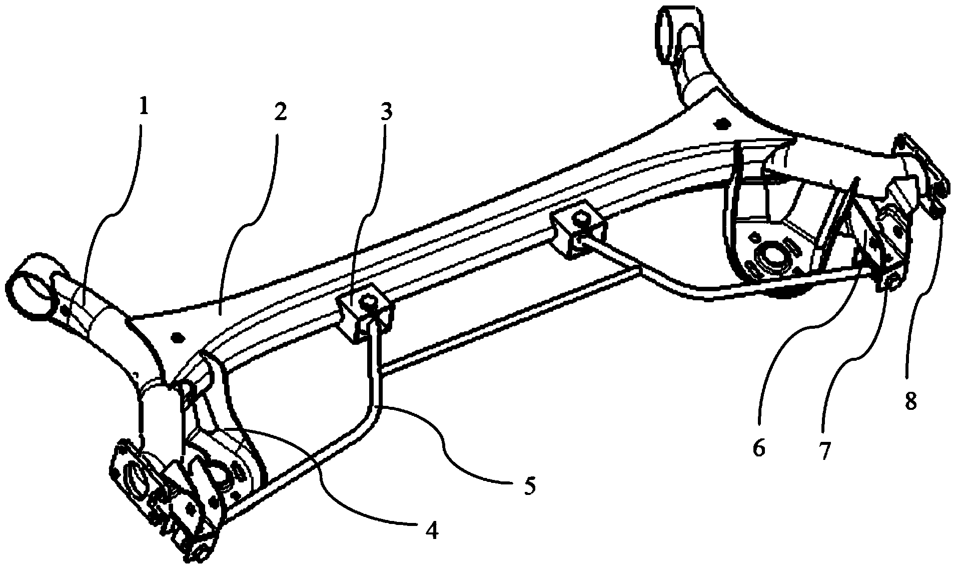
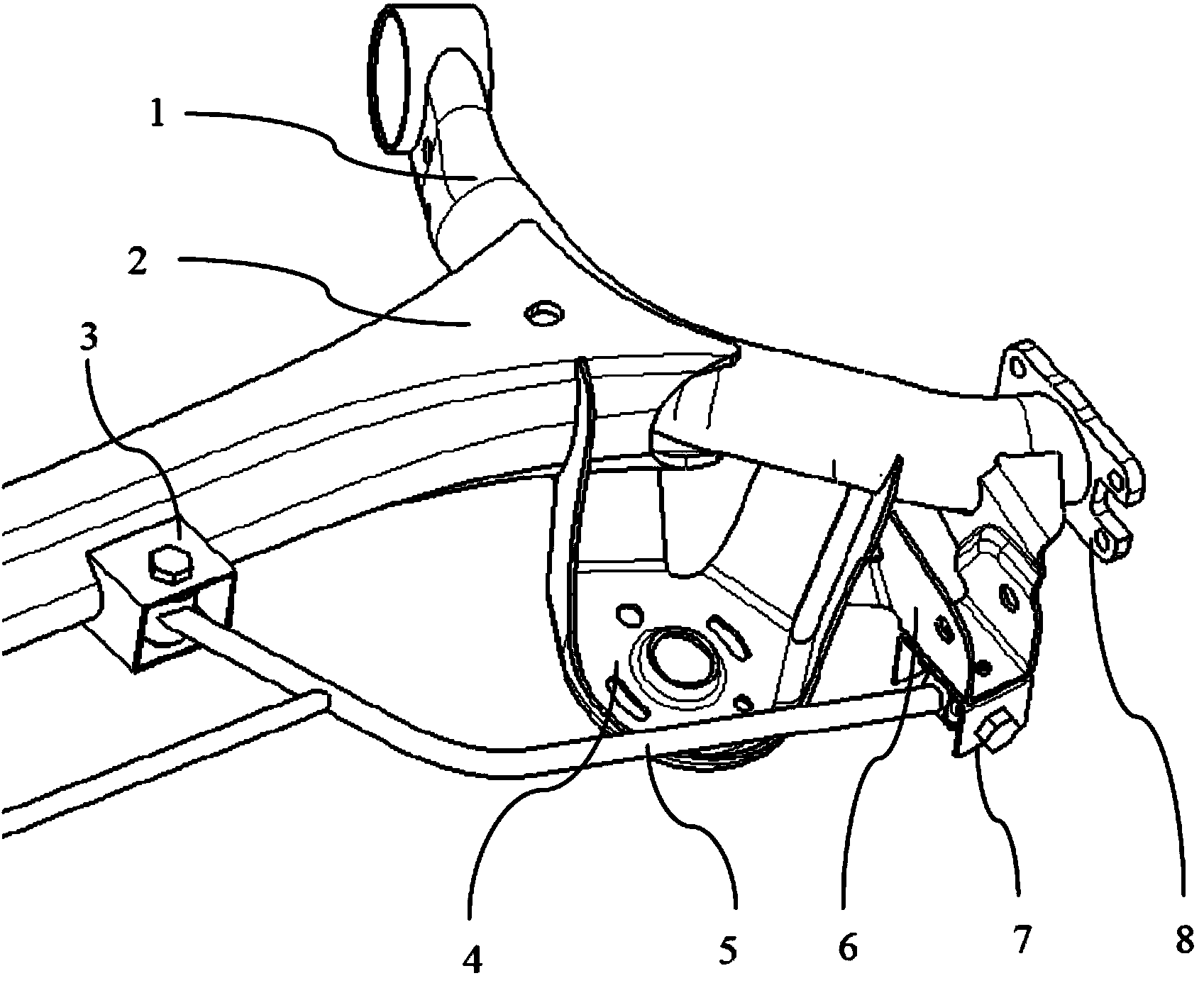
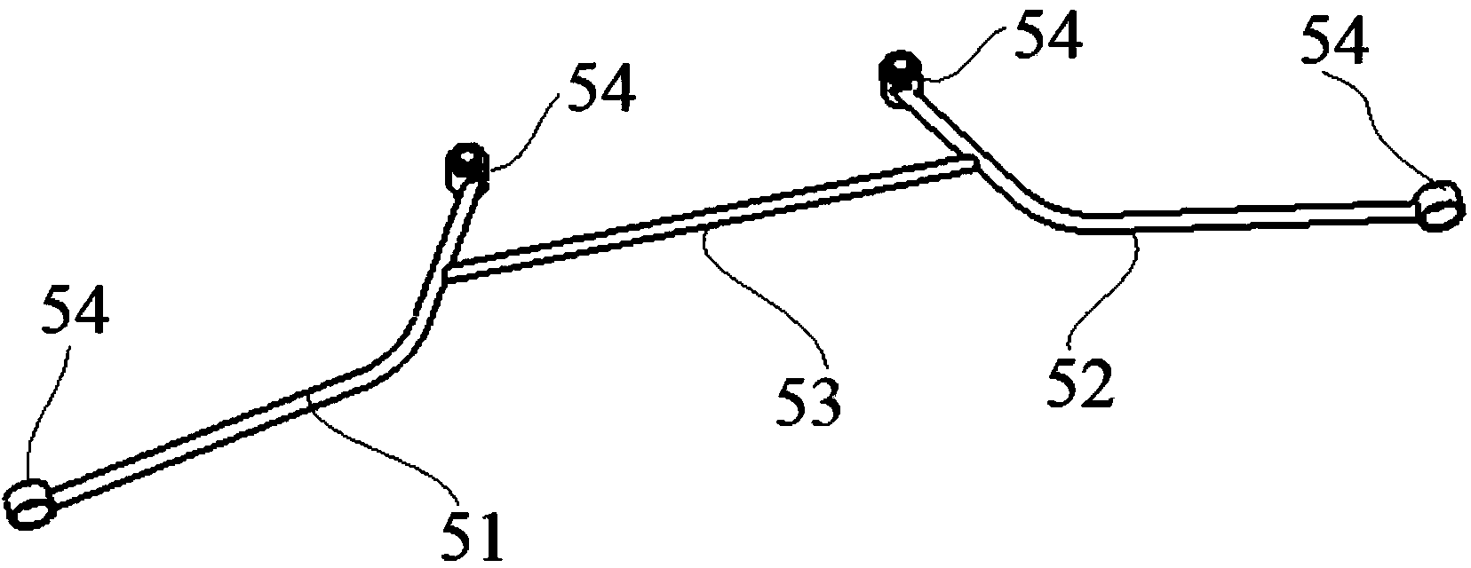
[0022] Such as Figure 1 to Figure 6 As shown, an automobile torsion beam suspension of the present invention is mainly composed of a suspension beam 2, a suspension longitudinal beam 1, a spring base 4, a shock absorber mounting bracket 6, a wheel mounting plate 8, a stabilizer cross bar 5 and other components. The suspension is symmetrical. The two suspension longitudinal beams 1 are respectively welded and connected to one end of the suspension beam 2, and the stabilizer beam 5 is located between the two suspension longitudinal beams 1 and is rotatably connected with the suspension beam 2 and the suspension longitudinal beam 1.

[0023] Specifically, the suspension beam 2 is a sheet metal stamped part, and the shape is an open U-shaped groove or a V-shaped groove. The thickness and shape of the sheet metal of the suspension beam 2 need to be determined according to the roll stiffness and strength requirements of the torsion beam suspension. The roll stiffness provided by the ...


PUM


Abstract

The invention discloses an automobile torsion beam suspension frame. The automobile torsion beam suspension frame comprises a suspension frame transverse beam and two suspension frame longitudinal beams respectively connected with the two ends of the suspension frame transverse beam respectively, and further comprises a stabilizing cross rod located between the two suspension frame longitudinal beams, and the stabilizing cross rod is rotationally connected with the suspension frame transverse beam and the suspension frame longitudinal beams. According to the automobile torsion beam suspension frame, the stabilizing cross rod is added, when an automobile swerves or passes through an uneven road, the large stress concentration is produced at the welding position of the suspension frame transverse beam and the suspension frame longitudinal beams due to torsion, the stabilizing cross rod can bear part of torque, and therefore the stress at the lap joints of the suspension frame transverse beam and the suspension frame longitudinal beams is reduced, and the cracking risk at the lap joints is reduced. The stabilizing cross rod of the automobile torsion beam suspension frame can be replaced, stabilizing cross rods with different torsion rigidities are replaced to a torsion beam assembly, the skew rigidity of the whole torsion beam suspension frame can be adjusted, the operating performance and the following rate of a back suspension frame are improved, cost is saved, and installing and maintaining are convenient.

Description

Technical field [0001] The invention belongs to the field of automobiles. Specifically, the invention relates to an automobile torsion beam suspension. Background technique [0002] The torsion beam suspension is mainly used as the rear suspension of the automobile. The existing torsion beam suspension is mainly made of V-shaped or U-shaped cross-section as the suspension beam, and its two ends are connected to the suspension longitudinal beam by welding to form an H-shaped Bearing frame, the front end of the suspension longitudinal beam is connected to the body through rubber bushes and bolts, and the rear end of the suspension longitudinal beam is connected with the hub, shock absorber and spring. Some torsion beam suspensions are designed to reduce the weld between the suspension beam and the suspension longitudinal beam. For the risk of cracking, a torsion bar is installed inside the V-shaped or U-shaped suspension beam and connected to the suspension longitudinal beam throug...

Claims


Application Information

Patent Timeline
IPC IPC(8): B60G21/055
Inventor 李鹏
Owner CHERY AUTOMOBILE CO LTD
Why Eureka
Try Eureka