
Autotrophic denitrifying nitrogen-removal reaction device, denitrification system and denitrification method of denitrification system

A technology of nitrification and denitrification, autotrophic denitrification, applied in chemical instruments and methods, water/sludge/sewage treatment, biological water/sewage treatment, etc. To achieve the effect of convenient operation, efficient denitrification treatment, and easy automatic control

Active Publication Date: 2015-04-15
EAST CHINA NORMAL UNIV
View PDF5 Cites 0 Cited by
  • Summary
  • Abstract
  • Description
  • Claims
  • Application Information

AI Technical Summary

Problems solved by technology

[0004] The invention overcomes the defects in the prior art that high amount of additional carbon source required for high carbon and nitrogen, high processing cost, and inability to achieve ideal biological denitrification effect in a low carbon-nitrogen ratio environment, etc., and proposes an autotrophic denitrification denitrification Nitrogen reaction device, nitrogen removal system and method for nitrogen removal

Method used


Image

  • Autotrophic denitrifying nitrogen-removal reaction device, denitrification system and denitrification method of denitrification system
  • Autotrophic denitrifying nitrogen-removal reaction device, denitrification system and denitrification method of denitrification system
  • Autotrophic denitrifying nitrogen-removal reaction device, denitrification system and denitrification method of denitrification system

Examples


Embodiment Construction

[0033] The present invention will be further described in detail in conjunction with the following specific embodiments and accompanying drawings. The process, conditions, experimental methods, etc. for implementing the present invention, except for the content specifically mentioned below, are common knowledge and common knowledge in this field, and the present invention has no special limitation content.

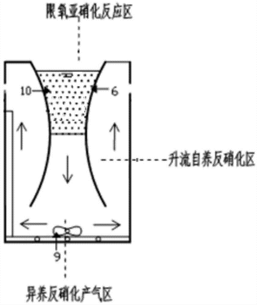
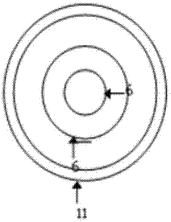
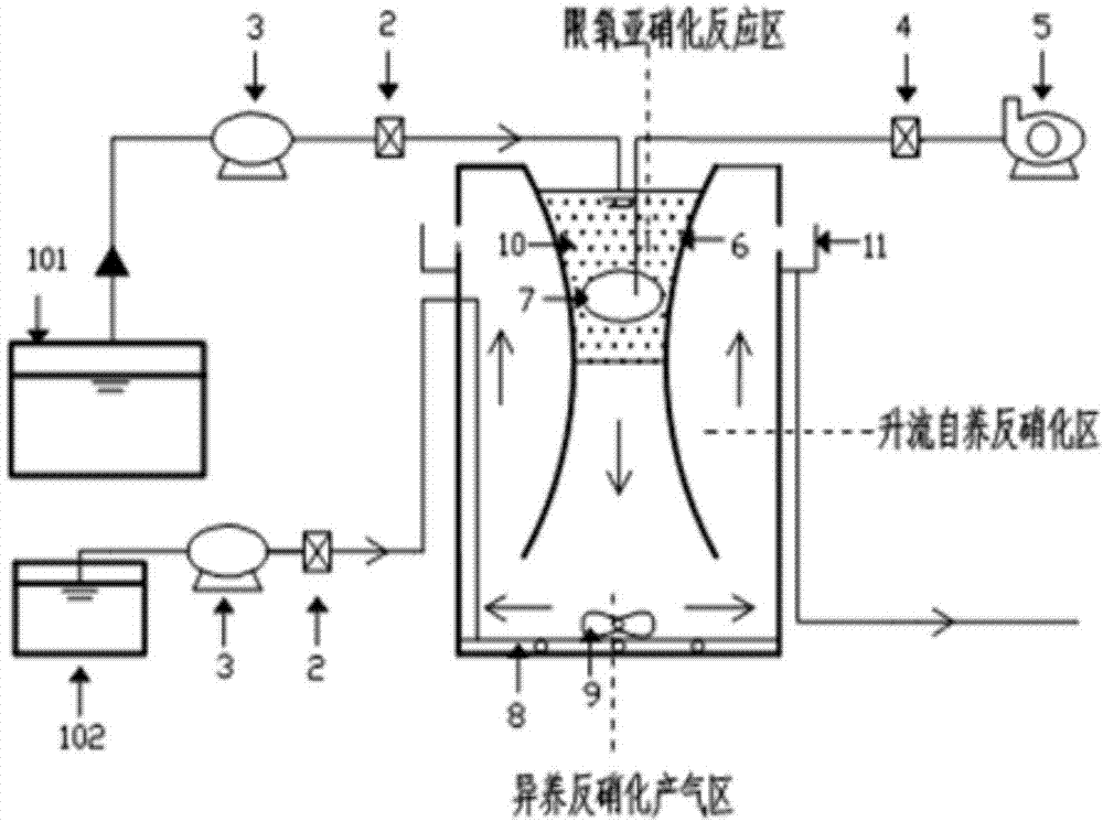
[0034] Such as figure 1 The shown autotrophic denitrification denitrification reaction device of the present invention includes a shell with a space inside the shell, and the space is divided into an oxygen-limited nitrosation reaction zone, a heterotrophic denitrification gas production zone and an upflow autotrophic denitrification zone. Area.

[0035] The housing is provided with a liquid inlet and several liquid outlets. The liquid inlet is connected to the oxygen-limited nitrosation reaction zone for feeding high ammonia nitrogen wastewater; the liquid outlet is conn...


PUM

PropertyMeasurementUnit
densityaaaaaaaaaa

Abstract

The invention discloses an autotrophic denitrifying nitrogen-removal reaction device. The autotrophic denitrifying nitrogen-removal reaction device comprises a housing, and an oxygen limited nitrosoation reaction region, a heterotrophic denitrification gas-producing region and an upflow autotrophic denitrification region all arranged in the housing; a liquid inlet and a liquid outlet are formed in the housing, and the liquid inlet is communicated with the oxygen limited nitrosoation reaction region; the liquid outlet is communicated with the upflow autotrophic denitrification region; the oxygen limited nitrosoation reaction region is arranged in the central region of the upper half part of the housing; the heterotrophic denitrification gas-producing region is arranged in a region under the oxygen limited nitrosoation reaction region and communicated with the oxygen limited nitrosoation reaction region; the upflow autotrophic denitrification region surrounds the oxygen limited nitrosoation reaction region and the bottom of the upflow autotrophic denitrification region is communicated with the heterotrophic denitrification gas-producing region. The invention also discloses a denitrification system and a denitrification method thereof. The autotrophic denitrifying nitrogen-removal reaction device, the denitrification system and the denitrification method of the denitrification system have the characteristics of high efficiency, large load and convenient operation, and also are low in operation cost, free of addition of lots of extra carbon source and prone to realize automatic control, and thus have practical application value for up-to-standard treatment and efficient low-consumption operation of high-nitrogen low-carbon wastewater.

Description

technical field [0001] The invention belongs to the field of sewage treatment devices and their use, and in particular relates to an autotrophic denitrification denitrification reaction device, a denitrification system and a denitrification method thereof. Background technique [0002] The traditional biological denitrification theory proposes that organic nitrogen in sewage is converted into NH by heterotrophic microorganisms 4 + -N, which is then converted to nitrate nitrogen NO by autotrophic nitrifying bacteria 2 - -N and NO 3 - -N, nitrate nitrogen is reduced and transformed into nitrogen gas by denitrifying bacteria under anoxic conditions, so as to achieve the purpose of denitrification of sewage. Sufficient carbon source is the key to the smooth denitrification process and efficient denitrification. When the carbon-nitrogen ratio (C / N ratio) in the wastewater is lower than 3.4, it is necessary to add an external carbon source to ensure a better biological denit...

Claims


Application Information

Patent Timeline
Patent Type & Authority Patents(China)
IPC IPC(8): C02F3/34C02F101/16
Inventor 谢冰杨盈盈张琪王佳欣王晓媛
Owner EAST CHINA NORMAL UNIV
Learn More