A high-strength guardrail

A high-strength, guardrail technology, used in building structures, stepped structures, buildings, etc., can solve the problems of complex guardrail structure, high cost, and inability to increase the strength of guardrails, and achieve the effect of ensuring strength, concise components, and simple structure

Active Publication Date: 2016-06-01
淮安泓臻金属科技有限公司
View PDF6 Cites 0 Cited by
  • Summary
  • Abstract
  • Description
  • Claims
  • Application Information

AI Technical Summary

Problems solved by technology

The structure of the guardrail is complicated, the cost is high, and the strength of the guardrail cannot be increased. After the external wood-plastic is broken, even if the metal is not broken, parts still need to be replaced

Method used


Image

  • A high-strength guardrail
  • A high-strength guardrail
  • A high-strength guardrail

Examples


Embodiment 1

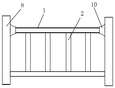
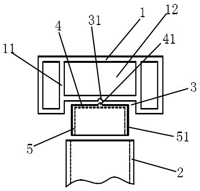
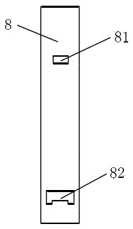
[0045] A high-strength guardrail, comprising a handrail 1, a lower link corresponding to the handrail 1, a plurality of railings 2 arranged between the handrail 1 and the lower link, and uprights 8 located at both ends of the handrail 1, characterized in that: the handrail 1 A mounting groove 3 adapted to the top of the railing 2 is provided at the bottom along the length of the handrail. The railing 2 is hollow to form an installation cavity. The mounting groove 3 is provided with a frame-shaped connector, and the frame-shaped connector includes a mounting on the top. The mounting plate 4 is fixed on the mounting groove 3 by screws, the frame-shaped connector is sleeved in the mounting cavity, the mounting groove 3 is a through groove, and the armrest 1 is hollow An armrest, the armrest 1 is provided with reinforcement ribs 11, a central cavity 12 is formed between the reinforcement ribs 11 and the hollow cavity wall of the armrest 1, and the upper part of the column 8 is provi...

Embodiment 2

[0048] The difference from the foregoing embodiment is that the limiting slot 31 is a single slot arranged on the same center line as the mounting slot 3, and the top surface of the mounting slot 3 is uniformly distributed with a grid line 32 along the limiting slot 31.

Embodiment 3

[0050] The difference from the above-mentioned embodiment is that the top surface of the mounting groove 3 is evenly distributed along the limiting groove 31 with equal dividing grooves 33 staggered with the limiting groove 31, and the top of the mounting plate 4 is provided with a dividing groove 33 Adapted evenly divided rib 42. The center of the mounting plate 4 is provided with a mounting hole for passing screws.

[0051] Due to the intersecting arrangement of the limit slot and the equalizing slot, it is ensured that the connecting piece will not rotate. In the design, the depth of the equalizing groove can be greater than the depth of the limiting groove, so that the positioning stability of the frame-shaped connector can be ensured under the premise of ensuring the strength of the armrest.


PUM


Abstract

The invention belongs to the field of fences and particularly relates to a high-strength fence which is simple in structure and convenient to install. The high-strength fence comprises an armrest, a lower connection rod corresponding to the armrest, a plurality of handrails arranged between the armrest and the lower connection rod, and vertical columns positioned at two ends of the armrest. Installation grooves matched with the tops of the handrails are formed in the bottom of the armrest in the length direction of the armrest, and the handrails are hollowed to form installation cavities. Box-shaped connection parts are arranged on the installation grooves and comprise installation plates positioned at the tops and box wall plates, the installation plates are fixed on the installation grooves through screws, and the installation cavities are sleeved with the box-shaped connection parts. The installation grooves are through, the handrails are hollow, reinforcement ribs are arranged in the handrails, and central cavities are formed between the reinforcement ribs and the hollow cavity walls of the handrails. Clamping blocks clamped with the central cavities are arranged at the upper portions of the vertical columns, and inserting holes matched with the lower connection rod are formed in the lower portions of the vertical columns. The high-strength fence is simple in structure, concise in parts and convenient to manufacture and install. Furthermore, the mounted fence is stable, orderly, strong in integrality and attractive.

Description

Technical field [0001] The invention belongs to the field of guardrails, and particularly relates to a high-strength guardrail with simple structure and convenient installation. Background technique [0002] The existing guardrails on the market are either simply manually positioned and spliced ​​and then screwed directly. Due to too many human factors, the guardrails are often not neatly spliced, individual guardrails are twisted or loose, or the existing ones are Railings with metal cores have a complex structure and high cost, and workers cannot accurately distribute the railings, and it is troublesome to adjust the spacing between the railings. And there will be the phenomenon of the railings moving out. For example, a metal core guardrail disclosed in Application Publication No. CN103046467A includes a column and a fence made of wood plastic. The fence is composed of upper and lower beams or upper and lower beams and longitudinal beams. The columns and the upper and lower b...

Claims


Application Information

Patent Timeline
Patent Type & Authority Patents(China)
IPC IPC(8): E04F11/18
Inventor 郑秀林
Owner 淮安泓臻金属科技有限公司
Why Eureka
Try Eureka