
External combustion propelling engine

A technology of engines and propulsion nozzles, which is applied in the direction of machines/engines, jet propulsion devices, etc., and can solve the problems of difficulty and high cost of engine manufacturing

Active Publication Date: 2014-07-23
JIANGSU ETERN
View PDF5 Cites 3 Cited by
  • Summary
  • Abstract
  • Description
  • Claims
  • Application Information

AI Technical Summary

Problems solved by technology

[0002] As the propulsion engine, it is usually a jet-type internal combustion engine, such as a turbojet engine, a turbofan engine, etc. These engines are expensive to manufacture and are not easy to use in some Special cases, such as single-use aircraft or simple aircraft

Method used


Image

  • External combustion propelling engine
  • External combustion propelling engine
  • External combustion propelling engine

Examples


Embodiment 1

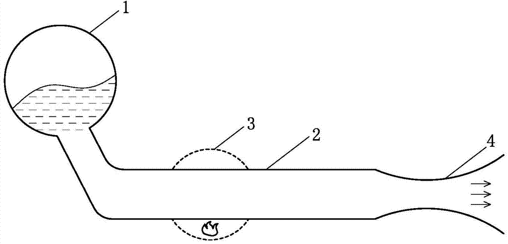
[0069] Such as figure 1 The external combustion propulsion engine shown includes a liquid working medium pressurized storage tank 1, a working medium heating fluid channel 2, a combustion chamber 3 and a propulsion nozzle 4, and the pressure bearing capacity of the liquid working medium pressurized storage tank 1 is greater than 2 MPa , the combustion chamber 3 is arranged for heat transfer to the working medium heating fluid passage 2, the working medium heating fluid passage 2 communicates with the propulsion nozzle 4, and the propulsion nozzle 4 outputs power externally, and the liquid working fluid The medium pressure storage tank 1 is in artesian communication with the working fluid heating fluid channel 2 .

Embodiment 2

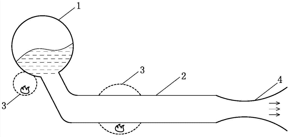
[0071] Such as figure 2 The difference between the external combustion propulsion engine shown in Embodiment 1 is that: the liquid working medium pressurized storage tank 1 is in artesian communication with the working medium heating fluid passage 2, and the combustion chamber 3 is connected to the liquid working medium The pressure storage tank 1 conducts heat.

[0072] As a changeable embodiment, it is also possible to make the liquid working medium pressurized storage tank 1 communicate with the working medium heating fluid passage 2, and the combustion chamber 3 transmits the pressure to the liquid working medium pressurized storage tank 1. hot.

Embodiment 3

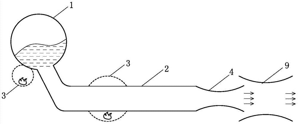
[0074] Such as image 3The external combustion propulsion engine shown, on the basis of Embodiment 2, further includes a jet pump 9 , and the working medium outlet of the propulsion nozzle 4 communicates with the motive fluid inlet of the jet pump 9 .

[0075] As a changeable implementation manner, the jet pump 9 can be set selectively on the basis of Embodiment 1 and the implementation manner obtained by transformation based on Embodiment 2 with reference to this embodiment.


PUM

PropertyMeasurementUnit
Pressure enduranceaaaaaaaaaa

Abstract

The invention discloses an external combustion propelling engine. The external combustion propelling engine comprises a liquid working medium pressure-bearing storage tank, a working medium heating fluid channel, a combustion chamber and a propelling nozzle. The bearing capacity of the liquid working medium pressure-bearing storage tank is larger than 2MPa. The combustion chamber transfers heat to the working medium heating fluid channel. The working medium heating fluid channel is communicated with the propelling nozzle. The propelling nozzle outputs power. The liquid working medium pressure-bearing storage tank is communicated with the working medium heating fluid channel in an automatically flowing mode. The combustion chamber transfers heat to the liquid working medium pressure-bearing storage tank or the pressure-bearing storage tank is communicated with the working medium heating fluid channel and the combustion chamber transfers heat to the liquid working medium pressure-bearing storage tank. The external combustion propelling engine is small in size, high in power density, low in manufacturing cost and capable of being used as an engine of aircrafts such as a target drone.

Description

technical field [0001] The invention relates to the field of thermal energy and power, in particular to an external combustion propulsion engine. Background technique [0002] As the engine for obtaining propulsion, it is usually a jet-type internal combustion engine, such as a turbojet engine, a turbofan engine, etc. These engines have high manufacturing costs and are not easy to be used in some special cases, such as disposable aircraft or simple aircraft. Therefore, need to invent a kind of novel engine that can obtain propulsion. Contents of the invention [0003] In order to solve the above problems, the technical scheme proposed by the present invention is as follows: [0004] Scheme 1: An external combustion propulsion engine, comprising a liquid working medium pressurized storage tank, a working medium heating fluid channel, a combustion chamber and a propulsion nozzle, the pressure bearing capacity of the liquid working medium pressurized storage tank is greater...

Claims


Application Information

Patent Timeline
IPC IPC(8): F02K7/00F02K5/00F02K3/065
Inventor 靳北彪
Owner JIANGSU ETERN
Learn More