Non-friction type transmission pair capable of separation and joining

A clutch transmission, non-friction technology, applied in the field of transmission pairs, can solve the problems of friction lining wear, reduce operating costs, short service life, etc., achieve the effect of strong torque transmission capacity, reduce operating costs, and avoid frequent maintenance

Active Publication Date: 2014-07-23
CHONGQING LONGWANG ELECTROMECHANICAL
View PDF6 Cites 1 Cited by
  • Summary
  • Abstract
  • Description
  • Claims
  • Application Information

AI Technical Summary

Problems solved by technology

[0002] At present, clutchable transmission pairs are mostly friction structures, and the clutch transmission is realized through the engagement and separation between the active friction plate and the driven friction plate, such as the clutch and brake of the vehicle, and these devices are in the driving process of the vehicle. Frequent operations are required to achieve effective control of the vehicle, and with the gradual increase in the number of vehicles, the smoothness of road traffic is getting worse and worse, and the operating frequency of clutches and brakes is increased, resulting in serious wear of the friction plates, requiring maintenance Frequent, but the replacement and installation of the friction plate is difficult, the operating cost is high, and the service life is short
[0003] Therefore, in order to solve the above problems, a non-friction clutchable transmission pair is needed to avoid the problems of frequent maintenance and short life due to component wear, and reduce operating costs.

Method used


Image

  • Non-friction type transmission pair capable of separation and joining
  • Non-friction type transmission pair capable of separation and joining

Examples


Embodiment Construction

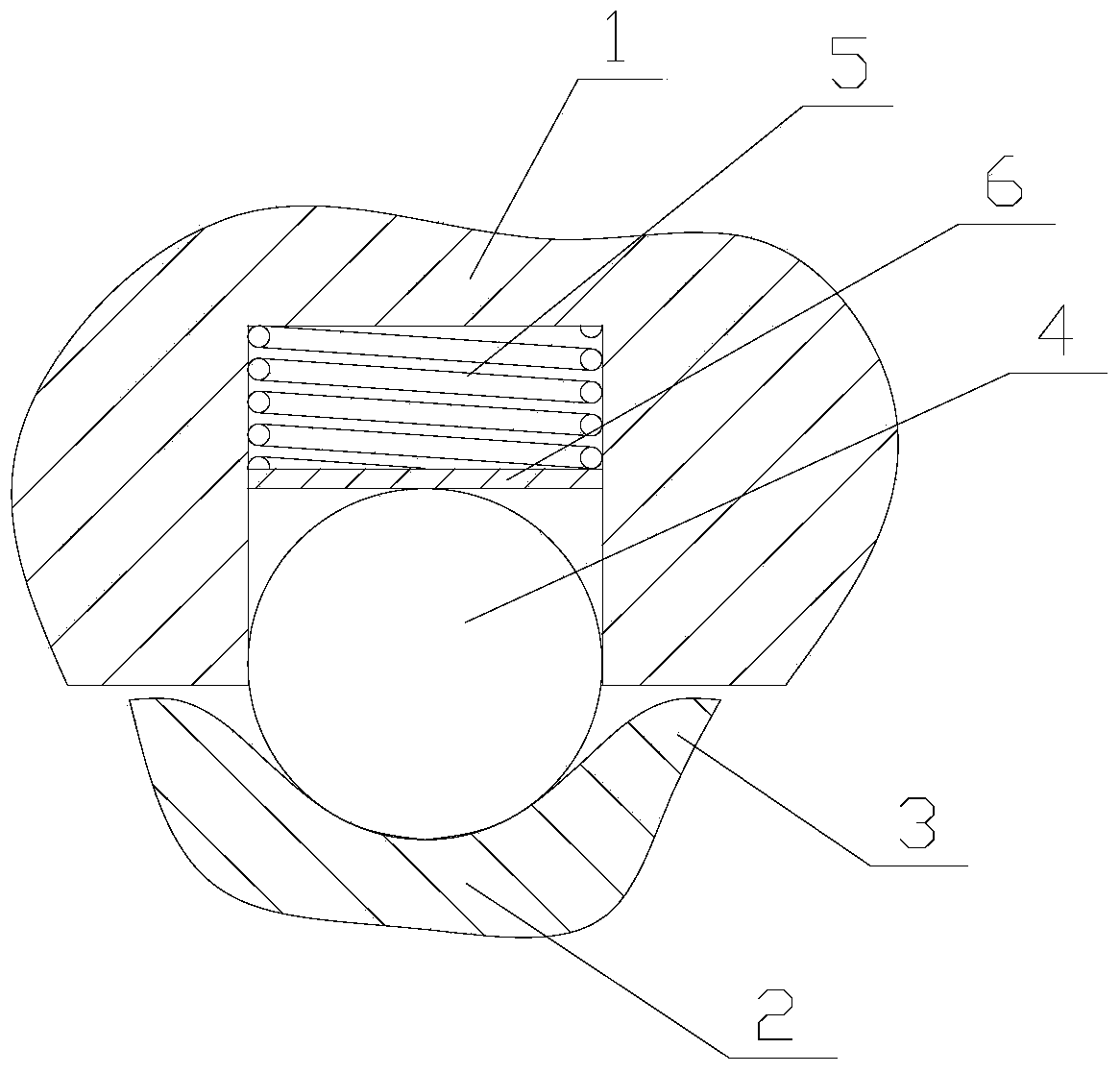
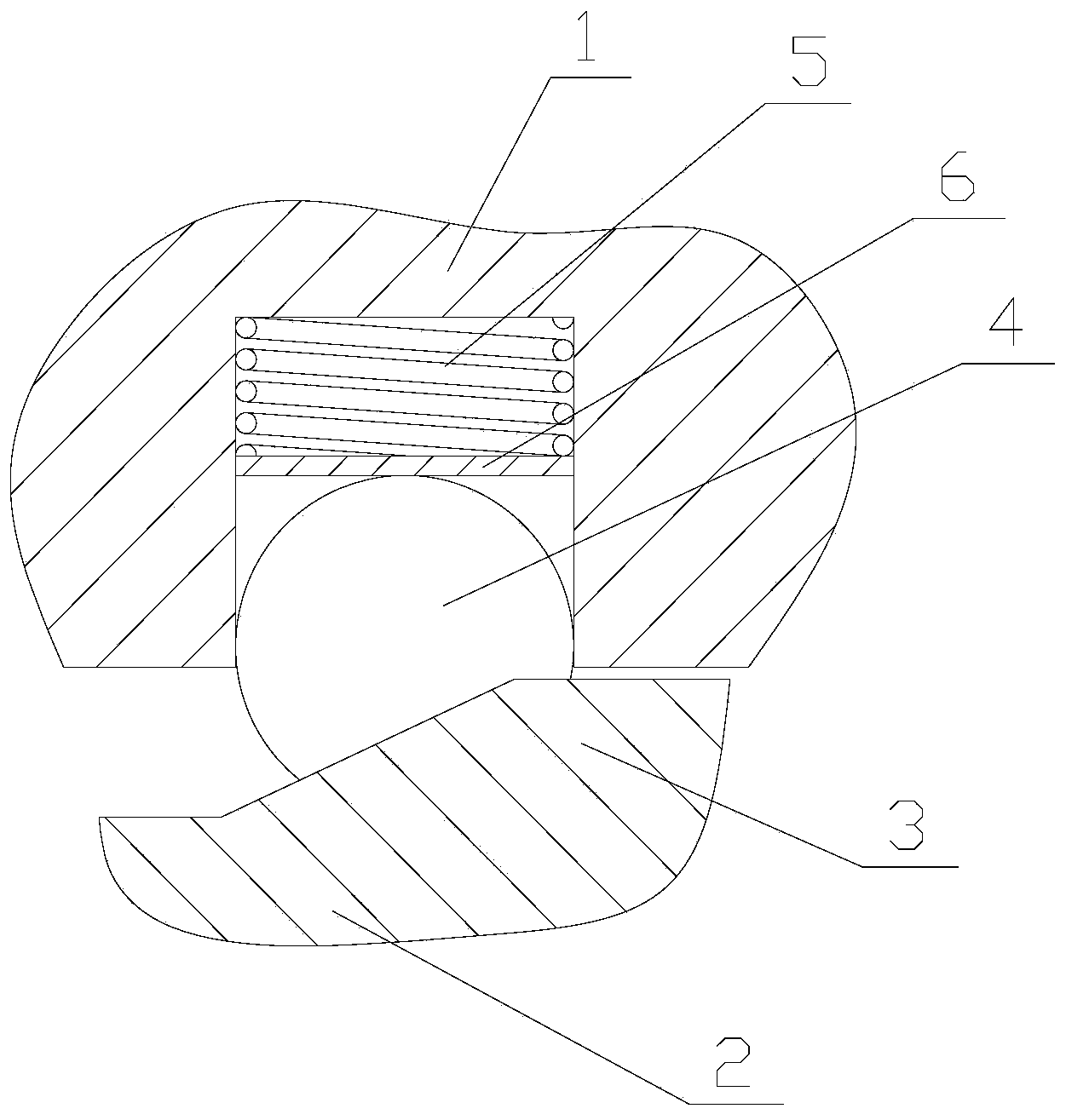
[0013] figure 1 It is a structural schematic diagram of the present invention; figure 2 for figure 1 The left side view; as shown in the figure: the non-friction clutchable transmission pair of this embodiment includes a primary rotating part 1, a secondary rotating part 2 and a transmission part; the primary rotating part 1 and the secondary rotating part 2 are coaxial Set together and rotationally fit, gear teeth 3 are provided on the rotational mating surface of the secondary rotating part 2; The floating block of the transmission; the tangential direction angle between the floating block and the point of action of the gear teeth 3 is continuously variable; the rotating mating surface of the secondary rotating part 2 refers to the matching between the secondary rotating part 2 and the primary rotating part 1 surface; the rotation mating surface of the primary rotating part 1 refers to the matching surface on the primary rotating part 1 and the secondary rotating part 2; ...


PUM


Abstract

The invention discloses a non-friction type transmission pair capable of separation and joining. The transmission pair comprises a primary rotating part, a secondary rotating part and a transmission part. The primary rotating part and the secondary rotating part are arranged together coaxially in a sleeved mode and are matched in a rotating mode. Wheel teeth are arranged on the rotating matching face of the secondary rotating part. The transmission part comprises a floating block which is arranged on the rotating matching face of the primary rotating part in a floating mode in the radial direction and is in meshing transmission with the wheel teeth. The tangential direction angle of the action points of the floating block and the wheel teeth is continuously changeable. The primary rotating part and the secondary rotating part are in separation-and-joining transmission through the transmission part. The tangential direction angle of the action points of the floating block and the wheel teeth is continuously changeable in a certain range, continuously-changeable joining force is generated, when the tangential direction angle is large, equal-torque output can be achieved, torque transmission capacity is high, the application range is wide, meanwhile, the floating block and the wheel teeth are matched in a non-friction mode, the problem that due to part abrasion, maintaining is frequent, and service life is short can be avoided, and operation cost is lowered.

Description

technical field [0001] The invention relates to a transmission pair, in particular to a non-friction clutchable transmission pair. Background technique [0002] At present, clutchable transmission pairs are mostly friction structures, and the clutch transmission is realized through the engagement and separation between the active friction plate and the driven friction plate, such as the clutch and brake of the vehicle, and these devices are in the driving process of the vehicle. Frequent operations are required to achieve effective control of the vehicle, and with the gradual increase in the number of vehicles, the smoothness of road traffic is getting worse and worse, and the operating frequency of clutches and brakes is increased, resulting in serious wear of the friction plates, requiring maintenance Frequent, but the replacement and installation of the friction plate is difficult, the operating cost is high, and the service life is short. [0003] Therefore, in order to...

Claims


Application Information

Patent Timeline
Patent Type & Authority Applications(China)
IPC IPC(8): F16D15/00
Inventor 郭军敬王吉龙
Owner CHONGQING LONGWANG ELECTROMECHANICAL
Why Eureka
Try Eureka