A microfluidic three-dimensional flow delay control unit

A three-dimensional flow and time-delay control technology, which is applied in the direction of analyzing materials and instruments, can solve problems such as the inability to realize linkage multiple detections, inconsistent liquid head flow rates, and poor functions, so as to shorten the experimental period, reduce personnel costs, and improve reliability effect

Active Publication Date: 2015-07-29
DALIAN UNIV OF TECH
View PDF6 Cites 0 Cited by
  • Summary
  • Abstract
  • Description
  • Claims
  • Application Information

AI Technical Summary

Problems solved by technology

However, the flow control units mentioned above are all composed of a simple two-dimensional microchannel structure, or even a single microchannel, which can only allow a relatively limited liquid to flow through the channel section, and cannot realize multiple detections in conjunction; at the same time It may also cause the liquid to be blocked by air bubbles in the flow delay control unit, the flow rate of the liquid head is inconsistent, and the function of controlling the delay flow of the liquid is not good

Method used


Image

  • A microfluidic three-dimensional flow delay control unit
  • A microfluidic three-dimensional flow delay control unit
  • A microfluidic three-dimensional flow delay control unit

Examples


Embodiment 1

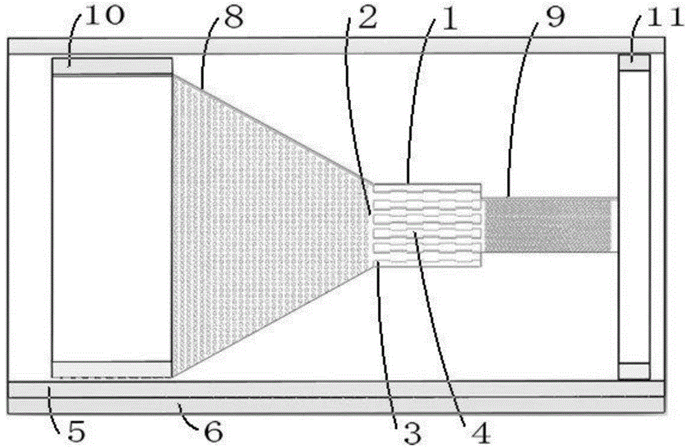
[0020] The microfluidic chip includes a mixing unit 8 , a three-dimensional flow delay control unit 1 , a detection unit 9 , a liquid storage pool 10 , and a waste liquid recovery pool 11 . The inlet of the three-dimensional flow delay control unit 1 is connected to the outlet of the mixing unit 8 , and the outlet of the three-dimensional flow delay control unit 1 is connected to the inlet of the detection unit 9 . The microstructures of the mixing unit 8 and the detection unit 9 are regularly distributed micro cylinder arrays, the diameter of the cylinders is 20 μm, the height of the cylinders is 10 μm, and the distance between the cylinders is 40 μm.

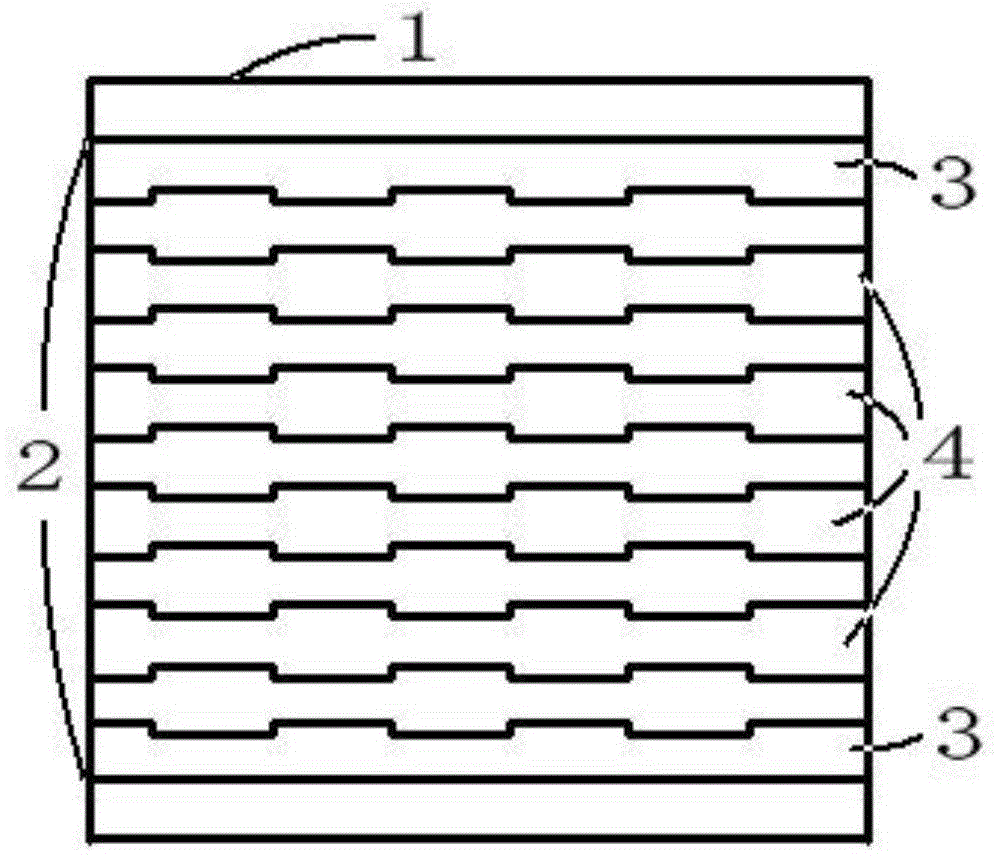
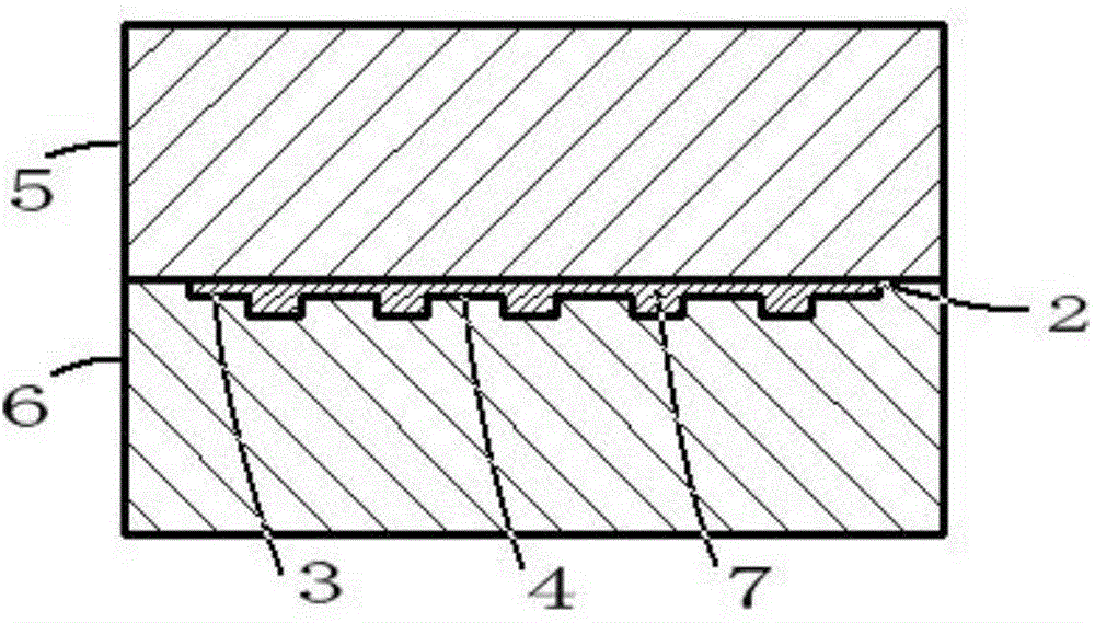
[0021] The microfluidic three-dimensional flow time-delay control unit 1 is composed of a channel 2 and tooth-shaped boss structures equally spaced on the channel. The height of the tooth-shaped boss structure is smaller than the depth of the channel 2, forming a three-dimensional structure; the channel 2 The depth is 20 μm, t...

Embodiment 2

[0026] The microfluidic chip includes a mixing unit 8 , a three-dimensional flow delay control unit 1 , a detection unit 9 , a liquid storage pool 10 , and a waste liquid recovery pool 11 . The inlet of the three-dimensional flow delay control unit 1 is connected to the outlet of the mixing unit 8 , and the outlet of the three-dimensional flow delay control unit 1 is connected to the inlet of the detection unit 9 . The microstructures of the mixing unit 8 and the detection unit 9 are regularly distributed micro cylinder arrays, the diameter of the cylinders is 200 μm, the height of the cylinders is 70 μm, and the distance between the cylinders is 400 μm.

[0027] The microfluidic three-dimensional flow time-delay control unit 1 is composed of a channel 2 and tooth-shaped boss structures equally spaced on the channel. The height of the tooth-shaped boss structure is smaller than the depth of the channel 2, forming a three-dimensional structure; the channel 2 The depth is 100 μm...

Embodiment 3

[0032] The microfluidic chip includes a mixing unit 8 , a three-dimensional flow delay control unit 1 , a detection unit 9 , a liquid storage pool 10 , and a waste liquid recovery pool 11 . The inlet of the three-dimensional flow delay control unit 1 is connected to the outlet of the mixing unit 8 , and the outlet of the three-dimensional flow delay control unit 1 is connected to the inlet of the detection unit 9 . The microstructures of the mixing unit 8 and the detection unit 9 are regularly distributed micro cylinder arrays, the diameter of the cylinders is 500 μm, the height of the cylinders is 150 μm, and the distance between the cylinders is 800 μm.

[0033] The microfluidic three-dimensional flow time-delay control unit 1 is composed of a channel 2 and tooth-shaped boss structures equally spaced on the channel. The height of the tooth-shaped boss structure is smaller than the depth of the channel 2, forming a three-dimensional structure; the channel 2 The depth is 200 μ...


PUM

PropertyMeasurementUnit
depthaaaaaaaaaa
widthaaaaaaaaaa
lengthaaaaaaaaaa

Abstract

The present invention provides a microfluidic three-dimensional flow delay control unit, and belongs to the field of micro total analysis. The microfluidic three-dimensional flow delay control unit comprises a channel and tooth-shaped boss structures laterally distributed on the channel at equal intervals, wherein the height of the tooth-shaped boss structure is less than the depth of the channel to form a three-dimensional structure, the length and the width of the channel are determined by the preset time for controlling a liquid to stay at the microfluidic three-dimensional flow delay control unit, and the tooth-shaped boss structures are the single-side tooth-shaped boss structures on both sides of the channel and the double-side tooth-shaped boss structures in the middle of the channel. According to the present invention, the liquid flow rate can be accurately controlled, the uniformity of the flow rate of the water head flowing through the same cross section of the microfluidic three-dimensional flow delay control unit is ensured, and the microfluidic three-dimensional flow delay control unit can be integrated into the microfluidic chip and can be used in the field of point of care teasting so as to rapidly obtain the experiment result and shorten the experiment period; and the microfluidic chip provides customized detection for patients so as to avoid interference of other factors and improve the reliability of the detection result.

Description

technical field [0001] The invention relates to a microfluidic three-dimensional flow delay control unit, which belongs to the field of micro-total analysis, in particular to the field of immune analysis and detection of microfluidic chips. Background technique [0002] At present, the control of liquid flow rate in microfluidic chips is mainly used in self-sampling microanalysis systems, such as biosensors, biochips, and high-throughput screening. The method of driving liquid flow is divided into active driving and passive driving. The flow rate control unit prepared by the active drive, the so-called microvalve, uses magnetic, electric, piezoelectric, thermal and other methods to drive the liquid to control the speed of the liquid flowing through the area. However, external devices need to be introduced, which increases the complexity of the microfluidic system and reduces the implantability. Passive drive, that is, without external equipment, directly uses capillary act...

Claims


Application Information

Patent Timeline
Patent Type & Authority Patents(China)
IPC IPC(8): G01N35/00
Inventor 李经民甘露刘冲张皓周利杰马亚会
Owner DALIAN UNIV OF TECH
Why Eureka
Try Eureka