Zero-mode and line-mode time difference radiation net fault location method achieved only through voltage without relying on two-terminal synchronization

A technology of fault location and radiation network, applied in fault location, measurement of electrical variables, measurement of electricity and other directions, can solve the problems of high operating cost of double-ended traveling wave method and difficulty in calibrating the arrival time of reflected wave head

Active Publication Date: 2014-07-23
KUNMING UNIV OF SCI & TECH
View PDF10 Cites 26 Cited by
  • Summary
  • Abstract
  • Description
  • Claims
  • Application Information

AI Technical Summary

Problems solved by technology

[0004] The technical problem to be solved by the present invention is to provide a fault location method for zero- and line-mode time-difference radiation networks that only utilizes voltage and does not rely on double-terminal synchroni

Method used


Image

  • Zero-mode and line-mode time difference radiation net fault location method achieved only through voltage without relying on two-terminal synchronization
  • Zero-mode and line-mode time difference radiation net fault location method achieved only through voltage without relying on two-terminal synchronization
  • Zero-mode and line-mode time difference radiation net fault location method achieved only through voltage without relying on two-terminal synchronization

Examples


Embodiment 1

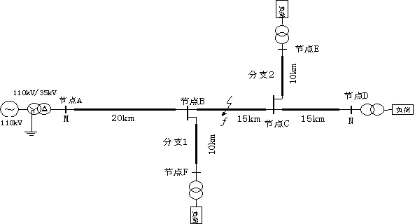
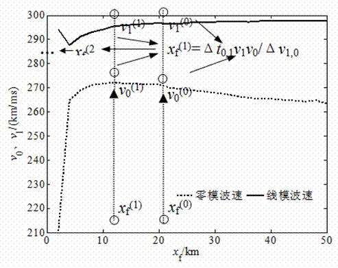
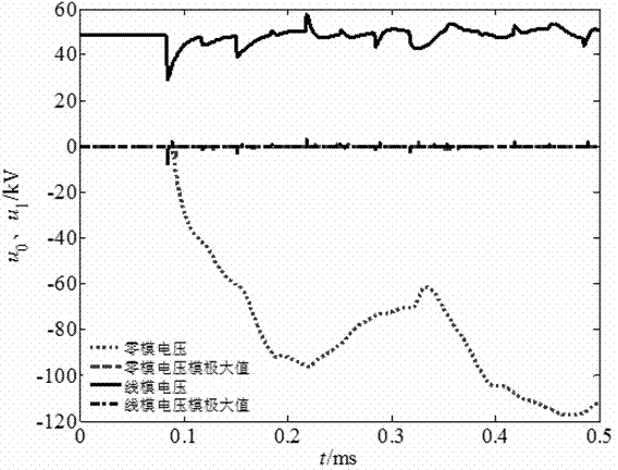
[0030] Example 1: Now assume that a single-phase grounded metal fault occurs on the trunk line 25km away from the M terminal, the initial phase angle of the fault is 90°, and the simulation sampling frequency is 10MHz, respectively use the wavelet modulus maximum value under the fifth scale to detect the measurement terminal Calibrate the time of the incoming line and zero-mode traveling wave components, and obtain the two measurement end lines of M and N, the zero-mode voltage traveling wave and its modulus maximum calibration as follows: image 3 shown. The arrival time difference of the M lateral line and zero-mode wave is △ t M = 0.0086ms, the time difference between N-side line and zero-mode wave is △ t N =0.0084ms, the wave velocity at the midpoint of the feeder is selected as the initial wave velocity iteration value, and the ranging formula is used Calculate the initial distance to fault x f (0) , the initial fault distance x f (0) Substituting the line and ...

Embodiment 2

[0031] Example 2: Assume that a single-phase grounded metal fault occurs on the branch 1 line 25km away from the M terminal, the initial phase angle of the fault is 50°, the fault transition resistance is 20Ω, and the simulation sampling frequency is 10MHz, respectively using the wavelet mode poles under the fifth scale The maximum value is time-calibrated for the line and zero-mode traveling wave components detected by the measuring end, and the two measuring end lines of M and N, the zero-mode voltage traveling wave and its modulus maximum value calibration are obtained. The arrival time difference between M side and N side line and zero-mode wave is △ t M and △ t N , select the wave velocity at the midpoint of the feeder as the initial wave velocity iterative value, and use the ranging formula Calculate the initial distance to fault x f (0) , the initial fault distance x f (0) Substituting the line and zero-mode interpolation curve for iteration, when the linear-m...


PUM


Abstract

The invention provides a zero-mode and line-mode time difference radiation net fault location method achieved only through voltage without relying on two-terminal synchronization, and belongs to the technical field of electric power system relay protection. Traveling wave fault distance measurement devices are arranged on the two sides of a feeder line, and fault distance measurement is conducted through information on the two sides. After grounding faults happen to the feeder line of a power distribution network, line-mode traveling components propagated between wires and zero-mode traveling wave components propagated between the wires and the ground are generated due to the sudden change of the voltage at the fault point. Due to the fact that the line-mode propagation velocity and the zero-mode propagation velocity are different, the arrival moment of the line-mode initial traveling wave and the arrival moment of the zero-mode initial traveling wave detected by a measurement terminal are different. Moment calibration is conduced through the wavelet modulus maximum under the fifth dimension according to the initial line-mode voltage traveling wave data and the initial zero-mode voltage traveling wave data detected by the measurement device, and the fault distance is calculated according to the ground fault single-terminal traveling wave fault location calculation formula for the modulus transmission time difference. Fault location is conducted by integrating single-terminal modulus propagation time difference distance measurement information on the two sides.

Description

technical field [0001] The invention relates to a method for locating faults in zero- and line-mode time-difference radiation networks that only utilizes voltage and does not rely on double-terminal synchronization, and belongs to the technical field of electric power system relay protection. Background technique [0002] Fault location after a fault occurs in the power grid can reduce the workload of manual line inspection, shorten the fault repair time, improve the reliability of power supply, reduce the loss of power outage, and find hidden dangers and deal with them as soon as possible to prevent the recurrence of faults. The method of fault location can be divided into fault analysis method and traveling wave method according to the principle of distance measurement. The core of the traveling wave method is to measure the propagation time of the traveling wave between the bus and the fault point to calculate the line fault distance. Traveling wave ranging can generally...

Claims


Application Information

Patent Timeline
IPC IPC(8): G01R31/08G01R31/02
Inventor 束洪春王瑶陈挥瀚
Owner KUNMING UNIV OF SCI & TECH
Why Eureka
Try Eureka