Electron beam emittance measuring equipment and measuring method

A technology of electron beam emission and measurement device, which is applied in the direction of measurement device, radiation measurement, X/γ/cosmic radiation measurement, etc., and can solve problems such as large influence of beam spot diameter measurement error, vacuum damage of accelerator pipeline, and increased work cycle. , to achieve the effect of improving vacuum sealing performance, improving stability and precision, and high stability and precision

Active Publication Date: 2014-07-23
INST OF FLUID PHYSICS CHINA ACAD OF ENG PHYSICS
View PDF8 Cites 6 Cited by
  • Summary
  • Abstract
  • Description
  • Claims
  • Application Information

AI Technical Summary

Problems solved by technology

The three-profile method is to measure the three profiles of the beam at three different positions on the beam axis, and then calculate the emissivity through matrix calculation. Since there are many unknowns in the process of solving the matrix, it is necessary to carry out the combination of these unknowns. Fitting to find a reasonable result. Due to the large number of unknowns, when the initial parameter range is unreasonable, the matrix equation may be an ill-conditioned equation. The various possibilities after the combination make the solution result have a large Instability, the solution process also has non-convergence, which makes the solution difficult; since the measurement needs to be carried out in a vacuum, every change of the measurement position will lead to the destruction of the vacuum of the accelerator pipeline and a large increase in the working cycle. With practical work experience, you can basically only measure one point a day when you work overtime; if you work in this way on a larger accelerator, the measurement cycle will be longer, which is not conducive to the maintenance of the accelerator
The three-gradient method is also a kind of three-profile method, which only fixes the beam profile measurement position on a plane on the beam axis, adjusts the diameter of the beam profile at the measurement position by changing the parameters of the upstream direction magnetic field, and simultaneously measures to obtain Three profile values, as attached to the manual figure 1 As shown, the emittance is calculated according to the solution method of the above matrix, so there are certain problems. Although this measurement method does not destroy the vacuum of the accelerator pipeline, the fitting parameters still include the changing magnetic field, and the parameters to be fitted are still relatively large. Many, if the parameters are not selected properly, the fitting results may be quite different, especially when measuring at the beam waist, the influence of the measurement error of the beam spot diameter is relatively large, as shown in the attached manual Figure 4 shown

Method used


Image

  • Electron beam emittance measuring equipment and measuring method
  • Electron beam emittance measuring equipment and measuring method
  • Electron beam emittance measuring equipment and measuring method

Examples


Embodiment

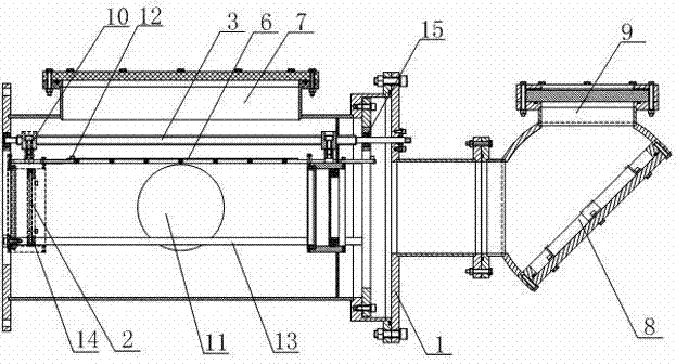
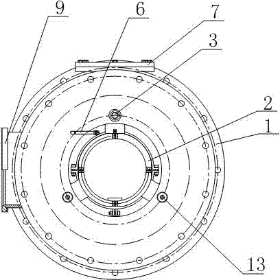
[0032] Such as Figures 2 to 3 As shown, an electron beam emissivity measuring device of the present invention includes a measurement target chamber 1, which is formed by surrounding a plurality of components, and is cylindrical in shape as a whole, and one end thereof is used as the injection end of the electron beam. Transparent glass is installed, and the other end is provided with two ring-shaped end faces with unequal diameters. In this section, a turning channel is connected through a flange, and a reflector 8 and a measuring window 9 are installed in the turning channel. The measuring window 9 is used to install a transparent quartz glass window, so that the luminescent image of the target can be sent out and taken by a camera placed on the side; a lead screw 3 is installed in the measurement target chamber 1, and the lead screw 3 is located above the axis of the measurement target chamber 1 One end of the lead screw 3 passes through the two ring-shaped end faces of une...


PUM


Abstract

The invention discloses electron beam emittance measuring equipment and an electron beam emittance measuring method. The electron beam emittance measuring equipment comprises a measuring target chamber, wherein the output end of the measuring target chamber is provided with a reflector and a measuring window, the measuring target chamber is further provided with a vacuum pump in which an energy conversion target capable of freely rotating along the axis of the target chamber and a measuring mechanism capable of measuring the position of the energy conversion target are arranged. According to the electron beam emittance measuring equipment, the number of parameters joining data fitting can be reduced to 1 by adopting a method of changing the measuring position under a fixed magnetic field parameter condition; furthermore, the mobile energy conversion target indicated by scales and a vacuum motive sealing mechanism are used to guarantee that the vacuum environment of the accelerator can not be damaged and the measurement position data is directly obtained when the measuring position is not changed, so that the working efficiency of the measurement can be greatly improved; in addition, the stability and precision of the fitting can be improved by adopting the way of increasing data measurement points through a plurality of position measurement data.

Description

technical field [0001] The invention relates to the field of accelerator development and parameter measurement, in particular to an electron beam emittance measurement device and a measurement method. Background technique [0002] In terms of accelerator development and parameter measurement technology research, the emittance parameter of charged particle beams is the most important parameter to characterize beam quality. Accurate measurement of electron beam emittance is of great significance to the debugging and improvement of accelerators. But its accurate measurement is indeed the most difficult task, the main reason is that the commonly used direct measurement method - the pepper hole method itself has some defects, such as the space charge effect, the existence of the pepper hole plate to change the emittance of the beam, the hole The distribution of the electron beam and its limitations, etc., because it has certain requirements on the electron beam current and is des...

Claims


Application Information

Patent Timeline
IPC IPC(8): G01T1/29
Inventor 江孝国王远李洪张卓杨兴林代志勇
Owner INST OF FLUID PHYSICS CHINA ACAD OF ENG PHYSICS
Why Eureka
Try Eureka