Rapid adjustment method of reflective concentric optical system

A technology of optical system and assembly method, which is applied in the direction of adopting optical devices, optics, optical components, etc., can solve the problems of complex process, high requirements for assembly environment, low efficiency and precision, etc., and achieve the improvement of assembly efficiency and intuitive performance and improve the efficiency of assembly and adjustment

Inactive Publication Date: 2014-07-23
CHANGCHUN INST OF OPTICS FINE MECHANICS & PHYSICS CHINESE ACAD OF SCI
View PDF1 Cites 8 Cited by
  • Summary
  • Abstract
  • Description
  • Claims
  • Application Information

AI Technical Summary

Problems solved by technology

[0004] In order to solve the problems of high installation and adjustment environment requirements, complicated process, low efficiency and low precision existing in the installation and adjustment of reflective concentric optical systems by the wavefront method, the present invention provides a rapid installation and adjustment method for reflective concentric optical systems

Method used


Image

  • Rapid adjustment method of reflective concentric optical system
  • Rapid adjustment method of reflective concentric optical system
  • Rapid adjustment method of reflective concentric optical system

Examples


Embodiment Construction

[0017] The present invention will be described in further detail below in conjunction with the accompanying drawings.

[0018] The quick installation and adjustment method of the reflective concentric optical system of the present invention is realized by the following steps:

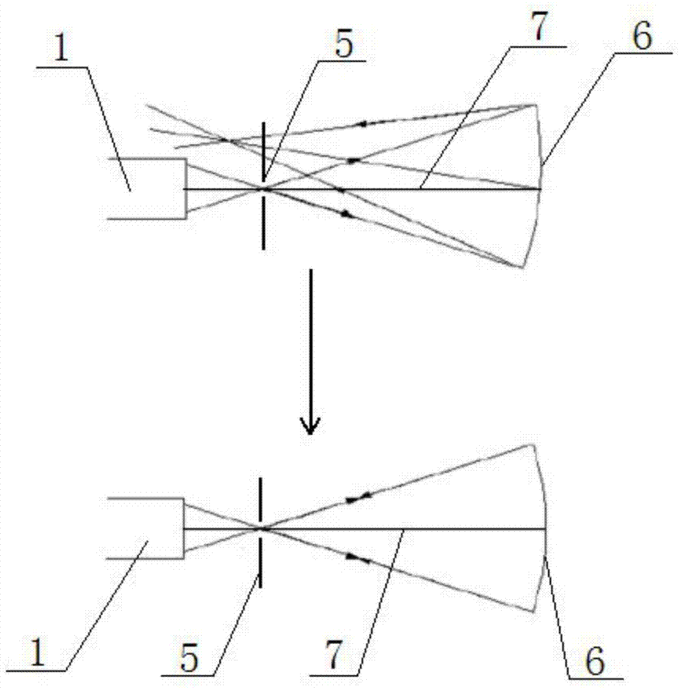
[0019] Step 1. Measure the axis 7 of the reflective concentric optical system

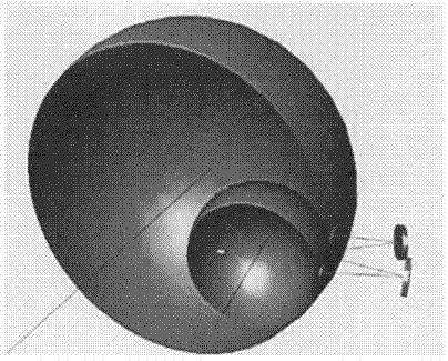
[0020] Such as figure 1 As shown, the autocollimated light of the autocollimator 1 is incident from the incident slit 5 through the reflective concentric optical system to the center of the detector 6 plane, and the line connecting the center of the incident slit 5 and the center of the detector 6 plane is the reflective concentric optical system. The axis 7 for the adjustment of the concentric optical system, through which the five degrees of freedom, three offsets and two angles of the reflective concentric optical system can be determined;

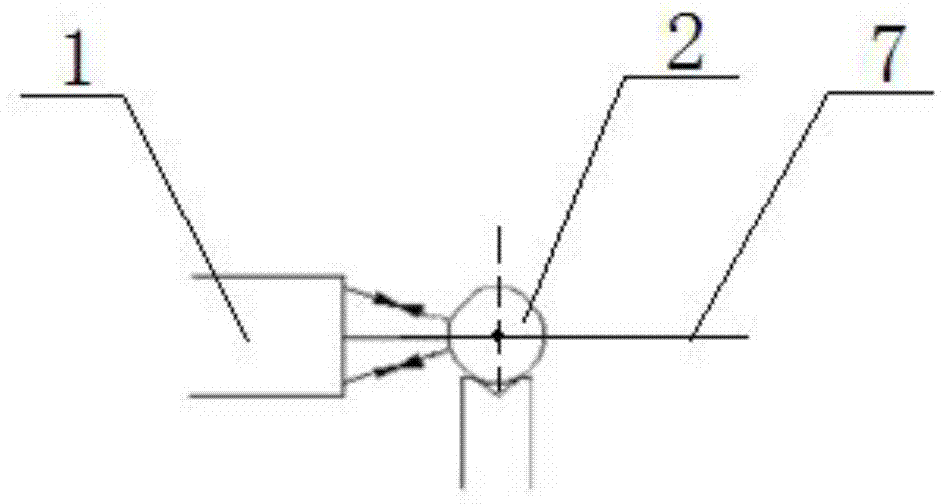
[0021] Step 2. Determine the position of the center of the sphere when the opti...


PUM


Abstract

The invention discloses a rapid adjustment method of a reflective concentric optical system, and relates to the field of adjustment of optical systems. The problems that a wave-front method is high in adjustment environment requirement, complex in process and low in efficiency and accuracy are solved. The method includes the steps that auto-collimation light of an autocollimator enters an entrance slit and then enters the center of the plane of a detector through the reflective concentric optical system, and the connecting line of the center of the entrance slit and the center of the plane of the detector is namely the adjustment axis of the reflective concentric optical system; the autocollimator aligns with the adjustment axis of the reflective concentric optical system, a positioning ball is adjusted to make the center of the ball located on the axis, wherein the center of the positioning ball is the position of the centers of the spheres of optical elements of the reflective concentric optical system when the optical elements are installed; the center of the sphere of a primary mirror and the center of the sphere of a third mirror are measured through the autocollimator, the spatial position of the primary mirror and the spatial position of the third mirror are respectively positioned through the positioning ball by the utilization of an auto-collimation image of the autocollimator, and the five degrees of freedom of the primary mirror and the third mirror are determined. The method has no special requirements for the adjustment temperature environment and the vibration environment, and adjustment efficiency is high.

Description

technical field [0001] The invention relates to the technical field of optical system installation and adjustment, in particular to a quick installation and adjustment method of a reflective concentric optical system. Background technique [0002] With the rapid development of aviation and aerospace optical imaging technology, reflective concentric optical system has been widely used due to its high light utilization rate, large effective aperture, and light structure. The concentric optical system consists of a series of refractive and reflective spherical optical elements with a common center of sphere. Obviously, any plane including the optical axis is the symmetry plane of the system, and any straight line passing through the sphere center is the rotational symmetry axis of the system. [0003] The existing adjustment method of the reflective concentric optical system is the wavefront method, that is, the interferometer is used to measure the wave aberration of the refle...

Claims


Application Information

Patent Timeline
Patent Type & Authority Applications(China)
IPC IPC(8): G02B27/62G02B27/30G02B7/182G01B11/00
Inventor 金辉马洪涛
Owner CHANGCHUN INST OF OPTICS FINE MECHANICS & PHYSICS CHINESE ACAD OF SCI
Why Eureka
Try Eureka