Fault diagnosis circuit and method of internal-drive electrically-controlled ignition system

An ignition system and diagnosis method technology, applied in the field of ignition coil fault diagnosis circuit, can solve the problems of increasing software complexity and risk, consuming MCU resources, etc., and achieve the effect of reducing after-sales maintenance costs

Active Publication Date: 2014-07-23
UNITED AUTOMOTIVE ELECTRONICS SYST
View PDF6 Cites 16 Cited by
  • Summary
  • Abstract
  • Description
  • Claims
  • Application Information

AI Technical Summary

Problems solved by technology

This solution consumes more MCU resources, but also increases software complexity and risk

Method used


Image

  • Fault diagnosis circuit and method of internal-drive electrically-controlled ignition system
  • Fault diagnosis circuit and method of internal-drive electrically-controlled ignition system
  • Fault diagnosis circuit and method of internal-drive electrically-controlled ignition system

Examples


Embodiment Construction

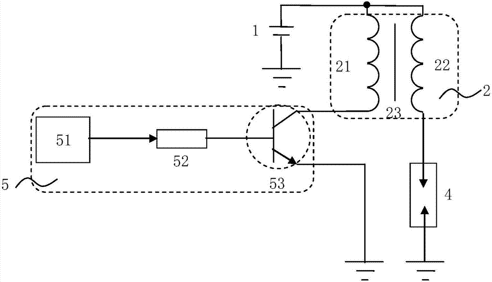
[0031] see Figure 3a , which is the first embodiment of the fault diagnosis circuit of the internal drive electric ignition system of the present application. This embodiment one is in such as Figure 1aOn the basis of the existing internal drive electronic control ignition system shown, a new sampling resistor 54, a comparator 55, a feedback resistor 56, a series resistor 57 and a series resistor 2 58 are newly added inside the ECU5 of the gasoline engine vehicle. Together constitute a fault diagnosis circuit. The feedback resistor 56, the first series resistor 57 and the second series resistor 58 are, for example, adjustable resistors. In the existing internal drive electronically controlled ignition system, the source or emitter of the switching device 53 is grounded. In this application, the source or emitter of the switching device 53 is changed to ground through the sampling resistor 54 on the one hand, and connected to the first input terminal of the comparator 55 th...


PUM


Abstract

The invention discloses a fault diagnosis circuit of an internal-drive electrically-controlled ignition system. The internal-drive electrically-controlled ignition system is structurally characterized in that a microcontroller, a first resistor and a switching element are arranged in an ECU of a vehicle, an output end of the microcontroller is connected with the grid of the switching element through the first resistor, and the drain or collector of the switching element is connected with one end of a primary coil. The fault diagnosis circuit is structurally characterized in that a sampling resistor, a comparator, series resistors and a feedback resistor are arranged in the ECU, the source or emitter of the switching device is connected with the ground through the sampling resistor and is connected with a first input end of the comparator through one series resistor, a second input end of the comparator is connected with the ground through the other series resistor, the feedback resistor is connected with a first input end of the comparator and the output end of the comparator, and the output end of the comparator is connected with an input end of the microcontroller. By means of the fault diagnosis circuit, ignition diagnosis of the internal-drive electrically-controlled ignition system can be achieved, ignition drive chips and the ECU are protected, after-sales maintenance cost is reduced, and economical and technical dual-benefits are acquired.

Description

technical field [0001] The present application relates to an electronically controlled ignition system of a gasoline engine, in particular to a fault diagnosis circuit and a diagnosis method of an ignition coil therein. Background technique [0002] The electronic control technology of gasoline engines has gradually developed into a comprehensive engine management system (EMS), which mainly includes electronic fuel injection (EFI), electronic ignition (ESA), etc. Among them, the electronically controlled ignition system collects various sensor signals installed on different parts of the engine by the electronic control unit (ECU) of the engine, judges the operating conditions of the engine, and selects the most ideal ignition advance angle to make the ignition coil ignite, thereby Improves the combustion process in the engine. [0003] In the electronically controlled ignition system, the ECU generates a relatively large drive current through the ignition drive circuit to d...

Claims


Application Information

Patent Timeline
Patent Type & Authority Applications(China)
IPC IPC(8): G05B23/02
Inventor 付逢春彭琴陆献忠于垂顺王帅於仕达
Owner UNITED AUTOMOTIVE ELECTRONICS SYST
Why Eureka
Try Eureka