Substrate connector and female header thereof

A substrate connector, female row technology, applied in the direction of connection, fixed/insulated contact member, coupling device, etc., can solve the problems of difficulty in achieving low profile and narrow spacing, complex substrate connector structure, and disadvantageous narrow spacing. , to achieve the effect of low profile and narrow spacing, simple low profile and narrow spacing, and improved support strength

Inactive Publication Date: 2014-07-23
가부시키가이샤타케우치기쥬쯔켄큐쇼
View PDF1 Cites 5 Cited by
  • Summary
  • Abstract
  • Description
  • Claims
  • Application Information

AI Technical Summary

Problems solved by technology

Regarding this point, the substrate connector of Patent Document 1 has a structure in which the spring piece of the female header contact is bent in a direction perpendicular to the insertion portion and contacts the insertion portion of the pin header contact, so the positive The size in the cross direction increases, which is not conducive to the realization of narrow pitch
[0007] In addition, in Patent Document 1, when the insertion p

Method used


Image

  • Substrate connector and female header thereof
  • Substrate connector and female header thereof
  • Substrate connector and female header thereof

Examples


Embodiment Construction

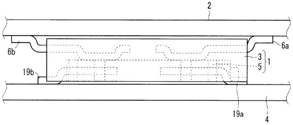
[0070] Hereinafter, embodiments of the present invention will be described with reference to the drawings. figure 1 It shows a form in which a circuit board is connected by the board connector of the first embodiment of the present invention. Such as figure 1 The illustrated board connector 1 has a header 3 mounted on a circuit board 2 and a socket 5 mounted on another circuit board 4 . The two circuit substrates 2 and 4 are electrically connected through the connection between the pin row 3 and the female row 5 .

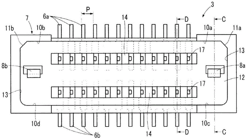
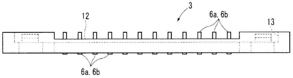
[0071] FIG. 2( a ) is a plan view of the pin header 3 . FIG. 2( b ) is a side view of the pin header 3 . Fig. 2(c) is a sectional view taken along line C-C in Fig. 2(a). Fig. 2(d) is a sectional view taken along line D-D of Fig. 2(a). FIG. 2( a ) shows the surface on the female header 5 side of the pin header 3 . The female header 5 is fixed on the surface of the female header 5 of the pin header 3 , so as to establish the connection between the pin header 3 ...


PUM


Abstract

The invention provides substrate connector. The substrate connector (1) is provided with a pin head (3) provided with a plurality of pin header contacts (6a)and(6b) and a female header (5) provided with a plurality of female header contacts (19a) and (19b). The female header contacts (19a) and (19b) are provided with female header side connecting part (28) extended along the length direction. The female header side connecting part (28) is provided with an inserting fixing hole (31) extended along the length direction. The inserting fixing hole (31) is formed by an inserting part (31a) and a press-in part (31b). The protrusions (17) the pin header contacts (6a)and(6b) are inserted in the inserting part (31a), and can move toward the length direction of the inserting fixing hole (31), and the protrusions (17) are disposed in the press-in part (31b) in a pressed manner. The substrate connector can be used to realize the low back and the narrow distance simply.

Description

technical field [0001] The present invention relates to a substrate connector for connecting circuit substrates and a substrate connector. Background technique [0002] In the prior art, as a board connector that electrically connects circuit boards such as printed boards, the following board connector is known (for example, refer to Japanese Patent Application Laid-Open No. 2008-27713): The female header of the contact piece and the pin header with a plurality of pin header contact pieces respectively connected to the female contact pieces of each row. [0003] In the board connector of Patent Document 1, the pin header contact includes a plurality of columnar insertion portions protruding toward the female header side. In addition, the female header contact includes first to third spring pieces that respectively contact the insertion portion from a direction perpendicular to the protruding direction of the insertion portion. Moreover, the connection between the pin heade...

Claims


Application Information

Patent Timeline
IPC IPC(8): H01R12/71H01R13/40
CPCH05K1/145H05K3/36H05K3/4697
Inventor 竹内忍
Owner 가부시키가이샤타케우치기쥬쯔켄큐쇼
Why Eureka
Try Eureka