Stator flux linkage observation method, electromagnetic torque observation method and devices utilizing two methods respectively

A stator flux linkage and electromagnetic torque technology, applied in the control of electromechanical transmission devices, electronic commutation motor control, electrical components, etc., can solve problems such as the inability to overcome the integral influence of the traditional voltage model flux observer

Active Publication Date: 2014-07-23
SUNGROW POWER SUPPLY CO LTD
View PDF2 Cites 14 Cited by
  • Summary
  • Abstract
  • Description
  • Claims
  • Application Information

AI Technical Summary

Problems solved by technology

[0004] In view of this, the present invention provides a stator flux linkage, electromagnetic torque observation method and a device for applying the two methods respectively, so as to solve the problem of integral influence of the traditional voltage model flux observer in the prior art, so as to realize the Problems of Speed ​​Sensorless Control of Permanent Magnet Synchronous Motor

Method used


Image

  • Stator flux linkage observation method, electromagnetic torque observation method and devices utilizing two methods respectively
  • Stator flux linkage observation method, electromagnetic torque observation method and devices utilizing two methods respectively
  • Stator flux linkage observation method, electromagnetic torque observation method and devices utilizing two methods respectively

Examples


Embodiment Construction

[0064] The following will clearly and completely describe the technical solutions in the embodiments of the present invention with reference to the accompanying drawings in the embodiments of the present invention. Obviously, the described embodiments are only some, not all, embodiments of the present invention. Based on the embodiments of the present invention, all other embodiments obtained by persons of ordinary skill in the art without making creative efforts belong to the protection scope of the present invention.

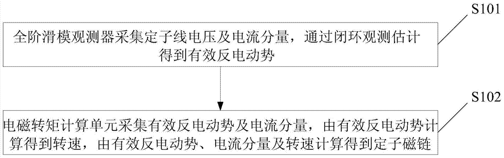
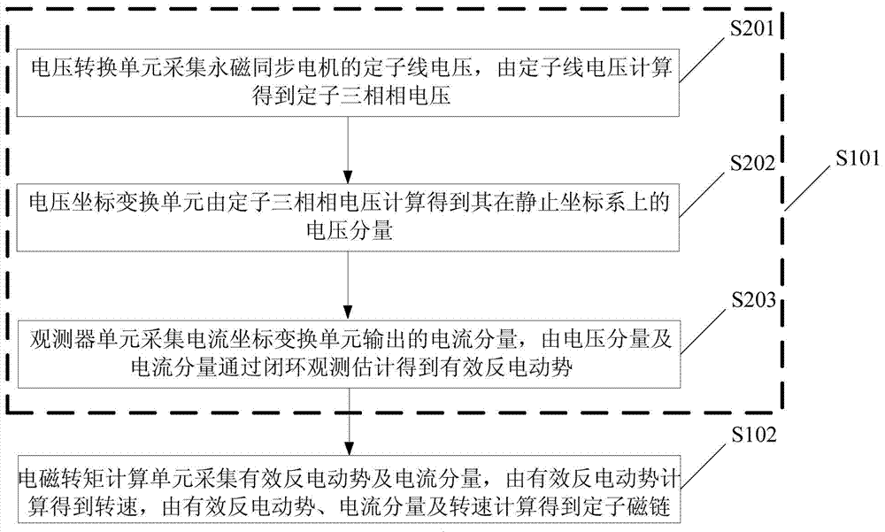
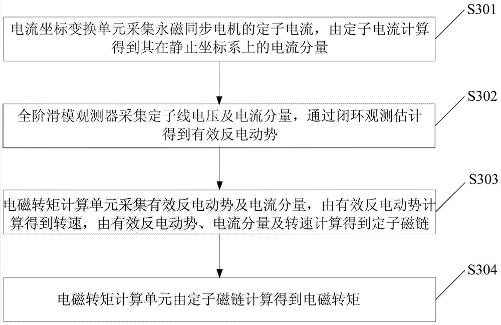
[0065] The invention provides a stator flux observation method to solve the problem in the prior art that the integral influence of the traditional voltage model flux observer cannot be overcome to realize the speed sensorless control of the permanent magnet synchronous motor.

[0066] The stator flux linkage observation method is applied to a digital signal processor, the digital signal processor is connected to the inverter and the permanent magnet synchronou...


PUM


Abstract

The invention discloses a stator flux linkage observation method, an electromagnetic torque observation method and devices utilizing the two methods respectively. A full-order slip form observer is utilized to collect line voltage uab and ubc of a stator of a permanent magnet synchronous motor and current components ialpha and ibeta which are output by a current coordinate conversion unit. Effective counter electromotive force (that img file=' DDA0000503801170000011. TIF' wi= '192' he= '74' / ) is obtained by closed loop observation estimation. The integral effect of a voltage model flux linkage observer in the prior art is removed. An electromagnetic torque calculation unit is utilized to collect the effective counter electromotive force (that img file= 'DDA0000503801170000012. TIF' wi= '176' he= '73' / ) and the current components ialpha and ibeta which are output by the current coordinate conversion unit. The effective counter electromotive force (that img file= 'DDA0000503801170000013. TIF' wi= '158' he= '71' / ) is utilized to calculate the rotating speed (that img file='DDA0000503801170000014. TIF' wi= '88' he= '80' / ), and then the effective counter electromotive force (that img file= 'DDA0000503801170000015. TIF' wi= '190' he= '72' / ), the current components ialpha and ibeta and the rotating speed (that img file= 'DDA0000503801170000016. TIF' wi= '62' he= '64' / ) are utilized to calculate the stator flux linkage (that img file= 'DDA0000503801170000017. TIF' wi= '216' he= '71' / ). By means of the method, the shortcoming in the prior art of the integral effect of the voltage model flux linkage observer is overcome, a speed sensor is not required, and speed-sensor-free stator flux linkage and electromagnetic torque observation is achieved.

Description

technical field [0001] The invention relates to the technical field of motor control, in particular to a method for observing stator flux linkage and electromagnetic torque and a device for respectively applying the two methods. Background technique [0002] In wind power generation technology, salient pole permanent magnet synchronous motors are widely used in wind power generation systems because of their advantages such as high power density and high reliability. In order to improve system reliability, wind power generation systems often require speed sensorless control. The electromagnetic torque closed-loop control method commonly used in the prior art has high electromagnetic torque control accuracy, but its electromagnetic torque feedback value is usually not directly Therefore, it is necessary to study the electromagnetic torque observation method without speed sensor. The electromagnetic torque can be obtained according to the stator flux linkage and stator current,...

Claims


Application Information

Patent Timeline
Patent Type & Authority Applications(China)
IPC IPC(8): H02P21/14
Inventor 屠运武张兴郭磊磊杨淑英邓立荣
Owner SUNGROW POWER SUPPLY CO LTD
Why Eureka
Try Eureka