Supercharge Your Innovation With Domain-Expert AI Agents!

Method and device for controlling an internal combustion engine

A technology for control devices and internal combustion engines, applied in fuel injection devices, internal combustion piston engines, electrical control, etc., can solve the problems of expensive and costly, achieve the effect of improving starting ability and simplifying the design

Inactive Publication Date: 2014-07-23
ROBERT BOSCH GMBH
View PDF8 Cites 0 Cited by
  • Summary
  • Abstract
  • Description
  • Claims
  • Application Information

AI Technical Summary

Problems solved by technology

In the case of such special fuels, such as E85, it is possible to use, for example, an additional cold start valve, which is complicated and expensive

Method used


Image

  • Method and device for controlling an internal combustion engine
  • Method and device for controlling an internal combustion engine

Examples


Embodiment Construction

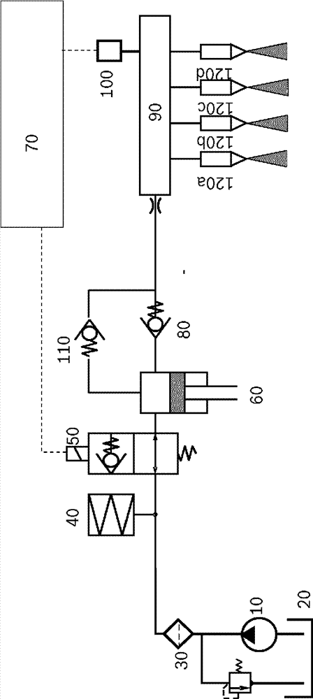
[0027] figure 1 An injection system is shown. Fuel is delivered by an electronic fuel pump 10 from a fuel tank 20 via a fuel filter 30 , a low-pressure buffer 40 and a flow control valve 50 to a high-pressure pump. The electronic fuel pump 10, the filter 30, the low pressure buffer 40 and the flow control valve 50 form the low pressure side of the injection system. The electronic fuel pump generates a pressure of several Bars, the low-pressure buffer 40 buffers pressure pulsations in a fuel line in which fuel is delivered, and the flow control valve 50 is regulated by a control device and / or The device 70 is controlled in such a way that it doses the desired or required fuel quantity. The high-pressure pump 60 delivers fuel via a check valve 80 to a fuel rail 90 . The high-pressure pump 60 generates pressures of up to several 100 Bar in this case. The pressure in the high-pressure rail 90 is detected by a rail pressure sensor 100 and transmitted back to the control and / or ...


PUM


Abstract

A method for starting an internal combustion engine, in which before a first ignition of a fuel- / air mixture, fuel is injected directly into the combustion chamber by means of multi-injection, wherein injection is carried out directly into the combustion chamber during an intake stroke in a first injection process and directly into the combustion chamber during a compression stroke in a second multi-injection process.

Description

technical field [0001] The invention relates to a method for operating an internal combustion engine. The subject-matter of the invention is also a computer program, an electrical storage medium and a control and / or regulation device. Background technique [0002] Otto engines with direct injection operate with injection pressures of up to 200 Bar. In this case, the pressure is set in the range of 40...200 Bar as a function of the operating point. To generate the high pressure, it is possible, for example, to use a system with a piston pump mechanically driven by the internal combustion engine, a flow control valve and a high pressure sensor. The delivery volume of the pump can be varied here via actuation of the flow control valve. Together with the measured high pressure signal, a control and / or regulating device regulates the pressure to the desired level. [0003] The injection valve is actuated based on the measured pressure signal. A cold start of a direct injecte...

Claims


Application Information

Patent Timeline
Patent Type & Authority Applications(China)
IPC IPC(8): F02D41/40F02D41/06F02M45/02F02D41/38F02D41/04
CPCF02D41/047F02D41/062F02D41/064F02D41/402F02D41/403F02D2041/389F02M63/0225Y02T10/40F02D19/024
Inventor G.波滕H-F.施瓦斯P.申克
Owner ROBERT BOSCH GMBH
Features
  • R&D
  • Intellectual Property
  • Life Sciences
  • Materials
  • Tech Scout
  • Unparalleled Data Quality
  • Higher Quality Content
  • 60% Fewer Hallucinations
Learn More