Electrically powered linear actuator

A linear actuator, electric technology, applied in the direction of transmission, gear transmission, transmission control, etc., can solve the problems of increased power loss, increased electric motor size and energy consumption, etc., to eliminate axial play, The effect of preventing run lock

Active Publication Date: 2014-07-23
NTN CORP
View PDF7 Cites 12 Cited by
  • Summary
  • Abstract
  • Description
  • Claims
  • Application Information

AI Technical Summary

Problems solved by technology

These motion conversion mechanisms include sliding contact parts, and thus increase power loss, thus necessitating an increase in electric motor size and energy consumption

Method used


Image

  • Electrically powered linear actuator
  • Electrically powered linear actuator
  • Electrically powered linear actuator

Examples


no. 1 approach

[0039] Hereinafter, preferred embodiments of the present invention will be described with reference to the accompanying drawings.

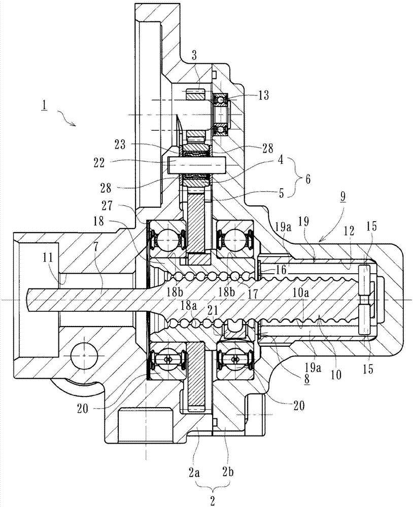
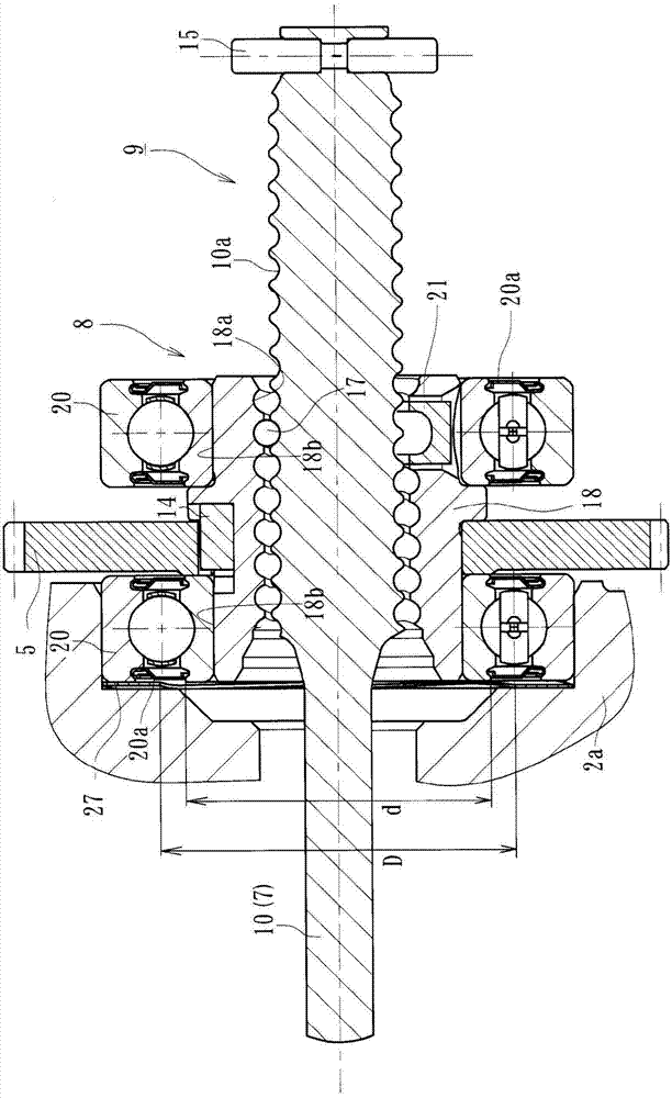
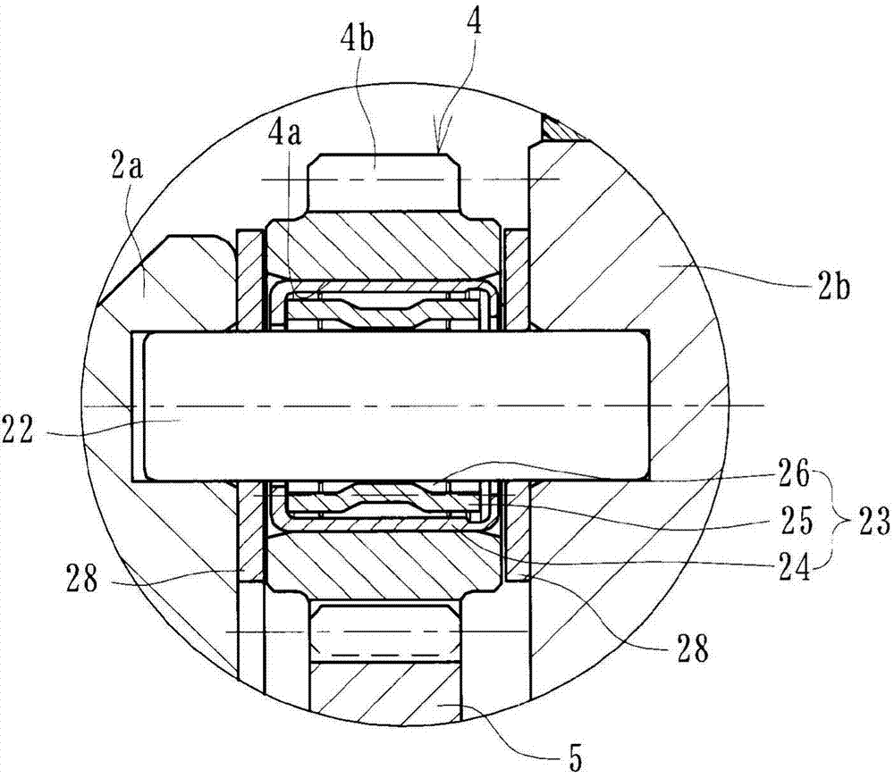
[0040] figure 1 is a longitudinal sectional view showing the first preferred embodiment of the electric linear actuator of the present invention, figure 2 is showing figure 1 Longitudinal sectional view of the actuator body of the electric linear actuator, image 3 is showing figure 1 A partial enlarged view of the intermediate gear of the electric linear actuator, and Figure 4 is showing image 3 A partial enlarged view of a variant of the intermediate gear.

[0041] Such as figure 1 As shown in , the electric linear actuator 1 includes: a casing 2 formed of light aluminum alloy; an electric motor (not shown) mounted on the casing 2; a speed reduction mechanism 6, which includes a The input gear 3 on the motor shaft (not shown) cooperates with the intermediate gear 4 and includes the output gear 5; a ball screw for converting the rot...

no. 2 approach

[0056] Figure 5 is a longitudinal sectional view showing a second preferred embodiment of the electric linear actuator of the present invention. The main difference between this embodiment and the first embodiment is only the structure of the supporting bearing and the washer, therefore, the same reference numerals as used in the first embodiment are also used in this embodiment to denote the same reference numerals as in the first embodiment. Those parts or parts having the same function as those parts or parts.

[0057] The electric linear actuator 31 includes: a housing 2 formed of light aluminum alloy; an electric motor (not shown); an intermediate gear 4 cooperating with an input gear 3 mounted on a motor shaft (not shown) of the electric motor; A reduction mechanism 6, which comprises an intermediate gear 4 and an output gear 5; a ball screw mechanism 8' for converting the rotational motion of the electric motor into an axial linear motion of the drive shaft 7 via the ...


PUM


Abstract

Provided is an electrically powered linear actuator, which averts ball screw lock up, is inexpensive and has excellent rotation performance. An output gear (5) configuring a deceleration mechanism (6) is fixed to a nut (18). Support bearings (20, 20) are disposed on both sides of the output gear (5) and the pair of support bearings (20, 20) are configured from a pair of roller bearings of the same specifications that can bear both thrust loads from the drive shaft (7) and radial loads applied through the output gear (5). The support bearings are installed in a housing (2a) via a washer (27), which is obtained from a ring-shaped elastic member. The internal diameter (D) of the washer (27) is formed to be larger than the external diameter (d) of the inner ring of the support bearing (20).

Description

technical field [0001] The present invention relates to an electric linear actuator provided with a ball screw mechanism used in driving parts of motors and automobiles in general industries, and more particularly relates to a method for converting rotational motion from an electric motor via a ball screw mechanism. An electric linear actuator used in a reducer or parking brake for the linear motion of a drive shaft. Background technique [0002] In electric linear actuators of various driving parts, a gear mechanism such as a trapezoidal screw worm mechanism or a rack and pinion mechanism is generally used as a mechanism for converting the rotational motion of an electric motor into an axial linear motion . These motion conversion mechanisms include sliding contact parts, and thus power loss increases, thus necessitating an increase in electric motor size and energy consumption. Therefore, the ball screw mechanism is widely adopted as a more efficient actuator. [0003] ...

Claims


Application Information

Patent Timeline
Patent Type & Authority Applications(China)
IPC IPC(8): F16H25/20F16H1/08F16H25/22
CPCF16H25/2204F16H1/06F16H25/20F16H2025/204F16H2025/2081Y10T74/18576F16H61/32F16H2063/3063
Inventor 池田良则
Owner NTN CORP
Why Eureka
Try Eureka