Method and system for controlling feeding speed of vibrating feeder

A vibrating feeder and feeding speed technology, applied in the field of control, can solve problems such as the inability to adjust the feeding speed, blockage of the crusher, engine flameout, etc., to avoid blockage of the crusher, increase the feeding speed, and reduce the feeding speed. The effect of material speed

Active Publication Date: 2017-02-15
XUZHOU XCMG MINING MACHINERY CO LTD
View PDF7 Cites 0 Cited by
  • Summary
  • Abstract
  • Description
  • Claims
  • Application Information

AI Technical Summary

Problems solved by technology

If the material is fed properly and the material enters the crushing cavity evenly, the crusher can achieve the highest efficiency; otherwise, the uneven feeding will cause the product to be too large, reduce the production capacity of the crusher, and also reduce the service life of the crusher
[0004] The feeding speed of the existing vibrating feeder is adjusted manually by monitoring the engine speed, and the feeding speed cannot be adjusted accurately according to the load change of the engine
When the engine load is too large, if the feeding speed is too fast, it will easily cause the engine to stall and the crusher will be blocked; when the engine load is too small, if the feeding speed is too slow, the operating efficiency of the crusher cannot be maximized , resulting in a waste of energy

Method used


Image

  • Method and system for controlling feeding speed of vibrating feeder
  • Method and system for controlling feeding speed of vibrating feeder
  • Method and system for controlling feeding speed of vibrating feeder

Examples


Embodiment Construction

[0040] The following will clearly and completely describe the technical solutions in the embodiments of the present invention with reference to the accompanying drawings in the embodiments of the present invention. Obviously, the described embodiments are only some, not all, embodiments of the present invention. Based on the embodiments of the present invention, all other embodiments obtained by persons of ordinary skill in the art without creative efforts fall within the protection scope of the present invention.

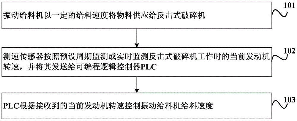
[0041] figure 1 It is a flow chart of an embodiment of the method for controlling the feeding speed of a vibrating feeder in the present invention. Such as figure 1 As shown, the control method of the vibrating feeder feeding speed provided by this embodiment includes:

[0042] Step 101, the vibrating feeder supplies the material to the impact crusher at a certain feeding speed; wherein, when the feeding speed is constant, the larger the particle size of the mate...


PUM


Abstract

The embodiment of the invention discloses a method and a system for controlling the feeding speed of a vibrating feeder. The method comprises the following steps: feeding materials to an impact crusher at a certain feeding speed by virtue of the vibrating feeder, wherein the larger the particle sizes of the materials are, the larger the load of an engine connected with the impact crusher is and the lower the rotating speed of the engine is under the condition that the feeding speed is constant; monitoring the current rotating speed of the engine during the working of the impact crusher according to a preset period or in real time by virtue of a speed measurement sensor, and sending the current rotating speed to a programmable logic controller (PLC); and controlling the feeding speed of the vibrating feeder according to the received current rotating speed of the engine by virtue of the PLC. According to the embodiment of the invention, the feeding speed of the vibrating feeder can be effectively controlled according to the intensity of the load of the engine, so that the automatic regulation of the feeding speed of the vibrating feeder is realized.

Description

technical field [0001] The invention relates to control technology, in particular to a method and system for controlling the feeding speed of a vibrating feeder. Background technique [0002] At present, mobile impact crushers are widely used in sand production and waste concrete recycling. The impact crusher is a crushing machine that uses impact energy to crush materials. When the impact crusher is working, the rotor rotates at a high speed. When the material enters the blow bar area, it collides with the blow bar on the rotor and breaks, and then is thrown to the impact device to be crushed again, and then bounces back to the blow bar from the impact liner. The action area is re-broken, and this process is repeated until the material is crushed to the required particle size and discharged from the discharge port. Adjusting the distance between the impact liner and the rotor can achieve the purpose of changing the material discharge particle size and material shape. [...

Claims


Application Information

Patent Timeline
Patent Type & Authority Patents(China)
IPC IPC(8): B02C25/00B02C23/02
Inventor 郑永生王志强蒋恒深覃杰
Owner XUZHOU XCMG MINING MACHINERY CO LTD
Why Eureka
Try Eureka