
Ladle bottom structure capable of reducing continuous casting ladle cast residues

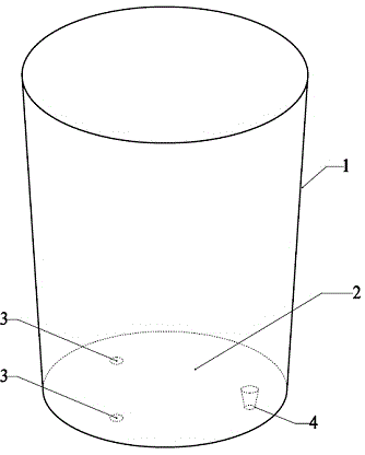
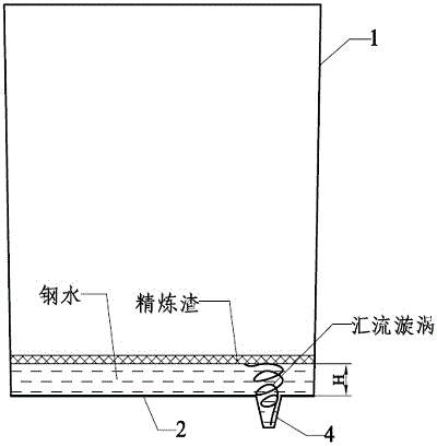
A technology of overcasting and continuous casting, which is applied in casting equipment, casting molten material containers, metal processing equipment, etc., and can solve the problems affecting the yield of molten steel and large casting allowance, so as to achieve less difficulty in masonry and reduce large ladle The effect of simple structure of casting residue and bottom cladding

Inactive Publication Date: 2014-07-30
张家港联峰钢铁研究所有限公司
View PDF6 Cites 2 Cited by
  • Summary
  • Abstract
  • Description
  • Claims
  • Application Information

AI Technical Summary

Problems solved by technology

In order to accurately judge the start time of slag discharge and close the ladle outlet in time, so as to control the slag discharge and reduce casting waste as much as possible, in addition to manual observation, a series of automatic detection methods for ladle slag discharge have been developed, such as electromagnetic detection method, vibration detection method, weighing detection method, ultrasonic detection method, infrared detection method, etc. However, at present, most of the ladle bottoms at home and abroad are flat masonry. There will be a large casting allowance, which will affect the yield of molten steel

Method used


Image

  • Ladle bottom structure capable of reducing continuous casting ladle cast residues
  • Ladle bottom structure capable of reducing continuous casting ladle cast residues
  • Ladle bottom structure capable of reducing continuous casting ladle cast residues

Examples


Embodiment 1

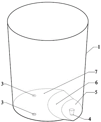
[0022] Example 1 : see image 3 , a clad bottom structure for reducing continuous casting ladle casting residue, the clad bottom and clad wall 1 together form a ladle inner cavity, the clad bottom structure includes a first plane 5, a second plane 7 and a transitional curved surface 6, The first plane 5 is provided with a large bag outlet 4, the second plane 7 is provided with a ventilating brick 3, the second plane 7 is higher than the first plane 5, and the transition curved surface 6 is provided on the first plane 5 and the second plane 7, the transition curved surface 6 connects the first plane 5 and the second plane 7. The transition between the first plane 5 and the second plane 7 is gentle, which ensures the circulation of molten steel in low-lying areas during argon blowing, avoids the formation of dead zones, and prevents the molten steel from being partially overcooled and resulting in freezing of the outlet.

Embodiment 2

[0023] Example 2 : see image 3 , as an improvement of the present invention, the first plane 5 is parallel to the second plane 7 . The rest of the structures and advantages are exactly the same as in Embodiment 1.

Embodiment 3

[0024] Example 3 : see image 3 , as an improvement of the present invention, the first plane 5 is a small area enclosed by two inferior arcs, in order to reduce the ladle casting residue to a greater extent, and its center is the ladle outlet 4 . The rest of the structures and advantages are exactly the same as in Embodiment 1.


PUM


Abstract

The invention relates to a ladle bottom structure capable of reducing continuous casting ladle cast residues. The ladle bottom structure is characterized in that a ladle bottom and ladle walls form a ladle inner cavity together; the ladle bottom structure comprises a first flat surface, a second flat surface and a transition curved surface; the first flat surface is internally provided with a ladle outlet; the second flat surface is internally provided with a vent brick; the second flat surface is higher than the first flat surface; the transition curved surface is connected with the first flat surface and the second flat surface. The ladle bottom structure has the following advantages: (1) ladle cast residues can be greatly reduced, and the cast residues can be reduced by above 70% on the premise of preventing ladle slagging; (2) the transition between the second flat surface and the first flat surface is smooth, so that circulation flow of molten steel in a low-lying area during an argon blowing process can be ensured; (3) the ladle bottom structure is relatively simple, less in construction difficulty and low in maintenance cost.

Description

technical field [0001] The invention relates to a clad bottom structure, in particular to a clad bottom structure capable of reducing casting waste of large continuous casting ladles, and belongs to the technical field of metal materials and processing. Background technique [0002] Ladle is one of the main equipments of continuous casting production, mainly used to contain molten steel, and the surface of molten steel is covered with refining slag. In addition to storing and transferring molten steel, ladles also have a series of molten steel refining functions such as argon blowing and stirring, temperature regulation, composition adjustment, and inclusion control. In the continuous casting process, molten steel flows out from the outlet of the ladle and enters the crystallizer through the tundish. Under the conditions of continuous casting and continuous cooling, the cast slab of the required shape is formed and cut to length, which becomes the billet for rolling steel. ...

Claims


Application Information

Patent Timeline
Patent Type & Authority Applications(China)
IPC IPC(8): B22D41/02
Inventor 陈远清张先轶宋健彭家清郭峰尚正鸿王进
Owner 张家港联峰钢铁研究所有限公司
Learn More