Automatic enveloping, jar mounting and welding device and method thereof

A welding equipment and welding method technology, which is applied in the field of automatic coating and slotting welding equipment, can solve the problems of low degree of automation, high labor intensity, affecting battery performance, etc., and achieve the goal of improving the degree of automation, improving work efficiency, and saving time and waiting. Effect

Active Publication Date: 2014-07-30
CHANGXING JINGSHENG HYDRAULIC MACHINERY
View PDF5 Cites 6 Cited by
  • Summary
  • Abstract
  • Description
  • Claims
  • Application Information

AI Technical Summary

Problems solved by technology

[0002] With the popularization of electric vehicles, the demand for batteries is increasing. In addition to the wrapping process, the main process of battery assembly production also includes coating, slotting and welding. At present, the equipment used by many domestic battery manufacturers is relatively backward. The degree of automation is small and the efficiency is low. Although foreign battery production equipment has a high degree of automation, the equipment investment cost is very high. Many battery manufacturers have no funds to purchase. At present, the battery manufacturing process is relatively simple, and there is no effective use of mutual cooperation between processes. , to achieve the purpose of saving time and improving efficiency. The current process of coating, slotting and welding is independent, and some processes cannot be completed at the same time. The production efficiency is low, the labor intensity is high, and the heating energy consumption of the electric furnace for automatic casting and welding is high. , Poor welding quality directly affects battery performance

Method used


Image

  • Automatic enveloping, jar mounting and welding device and method thereof
  • Automatic enveloping, jar mounting and welding device and method thereof
  • Automatic enveloping, jar mounting and welding device and method thereof

Examples


Embodiment Construction

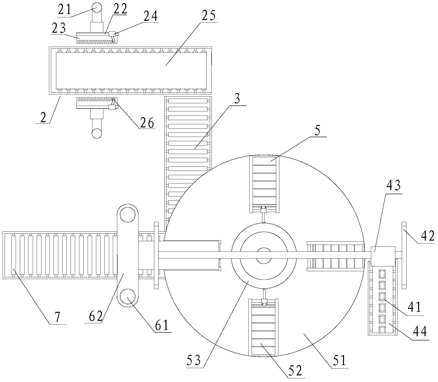
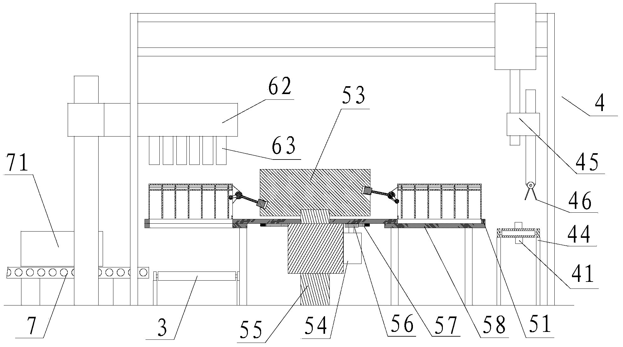
[0024] refer to figure 1 , figure 2 , image 3 , Figure 4 , Figure 5 and Figure 6 , a kind of automatic coating tank welding equipment of the present invention, comprises welding line 2, battery tank output conveyor belt 3, tank coating auxiliary mechanism 4, turntable mechanism 5 and battery tank loading mechanism 6, and described battery tank loading mechanism 6 is installed on One side of the turntable mechanism 5, the turntable mechanism 5 is installed with the trough coating auxiliary mechanism 4, and the trough coating auxiliary mechanism 4 includes a coating groove 41, a manipulator support 42, a transverse motor 43, a cluster conveyor belt 44, Vertical motor 45 and gripper 46, horizontal motor 43 is installed on the described manipulator support 42, and vertical motor 45 is installed on the bottom of horizontal motor 43, and gripper 46 is installed on the bottom of described vertical motor 45, is installed on the described cluster conveyer belt 44 There are se...


PUM


Abstract

The invention discloses an automatic enveloping, jar mounting and welding device and a method thereof. The device comprises a welding wire, a battery jar output conveyor, a jar mounting and enveloping auxiliary mechanism, a rotary plate mechanism and a battery jar mounting mechanism, wherein the rotary plate mechanism and the jar mounting and enveloping auxiliary mechanism are mounted in a matching manner; a horizontal motor is mounted on a mechanical hand bracket; a vertical motor is mounted at the lower part of the horizontal motor; a clamp is mounted at the lower part of the vertical motor; a plurality of enveloping tanks are mounted on a cluster conveyor belt; the battery jar output conveyor is mounted at the lower part of the rotary plate mechanism; one end of the battery jar output conveyor and the welding wire are mounted in a matching manner. The method comprises the following processes: cluster enveloping, cluster mounting clamps, cluster arrangement and clamping, conveying plastic battery jars, cluster mounting the battery jars, outputting the battery jars, flame welding and conversion operations of the batteries after welding. According to the automatic enveloping, jar mounting and welding device, the degree of automation of the device can be improved, the processes are arranged in a more reasonable manner and the production efficiency can be improved.

Description

【Technical field】 [0001] The invention relates to the technical field of storage battery production, in particular to the technical field of automatic coating and tank welding equipment and methods. 【Background technique】 [0002] With the popularization of electric vehicles, the demand for batteries is increasing. In addition to the wrapping process, the main process of battery assembly production also includes coating, slotting and welding. At present, the equipment used by many domestic battery manufacturers is relatively backward. The degree of automation is small and the efficiency is low. Although foreign battery production equipment has a high degree of automation, the equipment investment cost is very high. Many battery manufacturers have no funds to purchase. At present, the battery manufacturing process is relatively simple, and there is no effective use of mutual cooperation between processes. , to achieve the purpose of saving time and improving efficiency. The c...

Claims


Application Information

Patent Timeline
Patent Type & Authority Applications(China)
IPC IPC(8): B23K5/00B23K5/22H01M10/04
CPCB23K5/00B23K5/22B23K2101/36H01M10/04Y02P70/50
Inventor 陈桂云
Owner CHANGXING JINGSHENG HYDRAULIC MACHINERY
Why Eureka
Try Eureka