Safe and energy-saving electric welding machine control circuit system

A technology for controlling circuits and electric welding machines, applied in arc welding equipment, manufacturing tools, welding equipment, etc., can solve the problems of hidden safety hazards and high energy consumption, and achieve the advantages of improving safety, reducing no-load current and reducing energy consumption. Effect

Inactive Publication Date: 2014-07-30
STATE GRID CORP OF CHINA +1
View PDF10 Cites 1 Cited by
  • Summary
  • Abstract
  • Description
  • Claims
  • Application Information

AI Technical Summary

Problems solved by technology

[0003] The purpose of the present invention is to provide a safe and energy-saving electric welding machine control circuit system to solve the problem that the current electric welding machine control circuit has high energy consumption and certain hidden dangers in the operation process

Method used


Image

  • Safe and energy-saving electric welding machine control circuit system
  • Safe and energy-saving electric welding machine control circuit system
  • Safe and energy-saving electric welding machine control circuit system

Examples


Embodiment 1

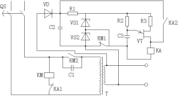
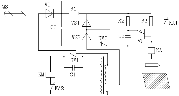
[0020] Such as figure 1 As shown, a safe and energy-saving welding machine control circuit system described in this embodiment includes a power switch QS, an AC contactor KM, a welding transformer T, and a relay KA. The power switch QS is set on the primary coil of the welding transformer T. The secondary coil of the transformer T is respectively connected to the welding torch and the welding body, such as figure 2 shown. The AC contactor KM has a normally closed contact KM1 and a normally open contact KM2, the relay KA has a normally closed contact KA1 and a normally open contact KA2, the normally closed contact of the AC contactor KM and the relay KA After KA1 is connected in series, it is connected in parallel at both ends of the primary coil of the electric welding transformer T, the normally open contact KM2 of the AC contactor KM is connected at the input end of the primary coil of the electric welding transformer T, and the two ends of the normally open contact KM2 of...

Embodiment 2

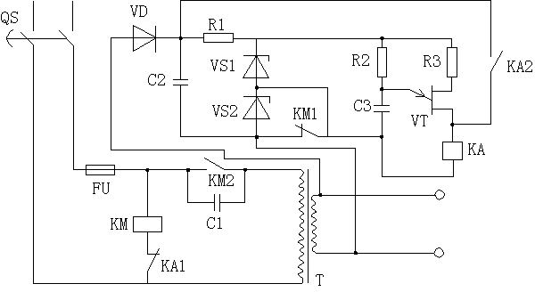
[0032] Such as image 3 As shown, this embodiment adds a fuse FU on the basis of Embodiment 1. One end of the fuse FU is connected to the power switch QS, and the other end is connected to the AC contactor KM. The fuse FU can protect the entire electric welding machine control circuit. The role of each device to avoid burning, but also to improve the safety of the entire circuit.


PUM

PropertyMeasurementUnit
capacitanceaaaaaaaaaa
electrical resistanceaaaaaaaaaa

Abstract

The invention discloses a safe and energy-saving electric welding machine control circuit system. The system comprises a power switch QS, an alternating current contactor KM, a welding transformer T and a relay KA, wherein the alternating current contactor KM and the normally closed contact KA1 of the relay KA are connected in series and then are connected with two ends of a primary coil of the welding transformer T in parallel; the normally open contact KM2 of the alternating current contactor KM is connected with the input end of the primary coil of the welding transformer T; capacitors C1 are connected with two ends of the normally open contact KM2 of the alternating current contactor KM in parallel; the system also comprises a resistor R1, a resistor R2, a resistor R3, a rectifying diode VD, a voltage stabilizing diode VS1, a voltage stabilizing diode VS2, a unijunction transistor VT, a capacitor C2 and a capacitor C3. By adopting the structure, the system can greatly reduce the no-load current of an electric welding machine, thereby reducing the energy consumption and achieving the purpose of energy conservation, and also can improve the safety of electric welding operation.

Description

technical field [0001] The invention relates to the field of electric welding machine control circuits, in particular to a safe and energy-saving electric welding machine control circuit system. Background technique [0002] The electric welding machine uses the high-temperature arc generated when the positive and negative poles are short-circuited instantaneously to melt the solder on the electrode and the material to be welded to achieve the purpose of combining them. The structure of the electric welding machine is not very complicated. In fact, it is equivalent to a high-power transformer, which turns the 220V AC voltage into a low-voltage, high-current power supply, which can be DC or AC. The current electric welding machine control circuit simply achieves the purpose of instantaneous voltage reduction. When the electric welding machine is unloaded, the current is relatively large, resulting in high energy consumption. In addition, the voltage is relatively high, and el...

Claims


Application Information

Patent Timeline
Patent Type & Authority Applications(China)
IPC IPC(8): B23K9/10
CPCB23K9/105
Inventor 刘明根徐登科穆举虎余强林利军龚斌曹武高治里郑超周敏杨梅李思伟卫飞黄恒李晨华肖文军但鹏
Owner STATE GRID CORP OF CHINA
Why Eureka
Try Eureka