Electric switching device for sample valve for chromatography

An electric switching and sampling valve technology, applied in valve device, valve operation/release device, measuring device, etc., can solve the problem of slow switching speed, manual switching of gas path can not be automatically controlled, cylinder-driven switching gas path switching angle cannot be Adjustment and other issues to achieve the effect of strong applicability, precise rotation control, and reasonable structure

Active Publication Date: 2014-07-30
XINJIANG GUANGLU ENERGY TECH CO LTD
View PDF6 Cites 2 Cited by
  • Summary
  • Abstract
  • Description
  • Claims
  • Application Information

AI Technical Summary

Problems solved by technology

[0003] The present invention provides an electric switching device for sampling valves for chromatography, which overcomes the above-mentioned deficiencies in the prior art, and can effectively solve the problem that manual switching of gas circuits cannot be automatically controlled , the switching speed is slow, and the switching angle of the cylinder drive switching gas circuit cannot be adjusted

Method used


Image

  • Electric switching device for sample valve for chromatography

Examples


Embodiment Construction

[0015] The present invention is not limited by the following examples, and specific implementation methods can be determined according to the technical solutions of the present invention and actual conditions.

[0016] In the present invention, for the convenience of description, the description of the relative positional relationship of each component is based on the description attached to the description. figure 1 The layout method is described, such as: the positional relationship of top, bottom, left, right, etc. is based on the attached figure 1 determined by the layout direction.

[0017] Below in conjunction with embodiment and accompanying drawing, the present invention will be further described:

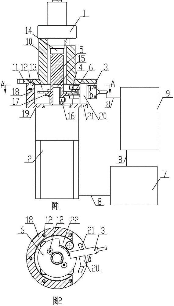
[0018] as attached figure 1 , 2 As shown, the electronic switching device for the injection valve for chromatography includes a mounting base, an injection valve for chromatography 1, a stepper motor 2, a photoelectric switch 3, a rotating shaft 5, a light s...


PUM


Abstract

The invention relates to the technical field of an electric switching driving device for a sample valve for chromatography, and belongs to an electric switching device for the sample valve for chromatography. The electric switching device for the sample valve for the chromatography comprises an installing seat body, the sample valve the chromatography, a step motor, a photoelectric switch, a rotating shaft, a light shielding sheet, a step motor driver and a controller, wherein the sample valve for chromatography is fixedly arranged at the upper end of the installing seat body, the step motor is fixedly arranged at the lower end of the installing seat body, a power output shaft arranged at the upper end of the step motor is in transmission connection with a valve rod arranged at the lower end of the sample valve for chromatography through the rotating shaft, and the rotating shaft is sheathed in the installing seat body. The electric switching device for the sample valve for chromatography has the advantages that the structure is reasonable and compact, the use is convenient, the step motor is controlled to rotate by the controller, in addition, the valve rod of the sample valve for chromatography is driven to rotate through the rotating shaft, and the air path switching is realized; the goals of automatic control and fast switching are achieved; meanwhile, the driving rotating angle of the step motor can be regulated through changing the parameters of the controller and the position of the photoelectric switch, the precise rotating control is realized on the sample valve for chromatography with different rotating angles, and the applicability is high.

Description

technical field [0001] The invention relates to the technical field of a sampling valve switching drive device for chromatography, and relates to an electric switching device for a sampling valve for chromatography. Background technique [0002] The sampling valve for chromatography is a gas path accessory of the gas chromatograph. It is usually used in conjunction with the quantitative tube as a gas sampling valve; when the gas sampling volume is large, it can make the gas quantification accurate and the data repeatability good; The injection valve for chromatography includes a valve body, a valve stem and a valve disc; there are multiple gas circuit joints evenly distributed on the circumference of the valve body, and the valve disc located in the valve body has holes corresponding to the gas circuit joints. There are interconnected passages in the disc; through the passages in the valve disc, the air joints are connected with each other and form an air communication mode;...

Claims


Application Information

Patent Timeline
Patent Type & Authority Applications(China)
IPC IPC(8): F16K31/04F16K37/00F16K11/072G01N30/20
CPCF16K31/046G01N30/20
Inventor 武志超张伟张柳
Owner XINJIANG GUANGLU ENERGY TECH CO LTD
Why Eureka
Try Eureka