Binocular photogrammetry method of large flexible structure vibration displacement

A technology of flexible structure and vibration displacement, which is applied in measuring devices, measuring ultrasonic/sonic/infrasonic waves, and interpretation of photos, etc. It can solve problems such as the influence of flexible structures on performance

Inactive Publication Date: 2014-07-30
HARBIN INST OF TECH
View PDF5 Cites 34 Cited by
  • Summary
  • Abstract
  • Description
  • Claims
  • Application Information

AI Technical Summary

Problems solved by technology

[0003] The purpose of the invention is to solve the problem that the existing contact measurement will affect the performance of the f

Method used


Image

  • Binocular photogrammetry method of large flexible structure vibration displacement
  • Binocular photogrammetry method of large flexible structure vibration displacement
  • Binocular photogrammetry method of large flexible structure vibration displacement

Examples


specific Embodiment approach 1

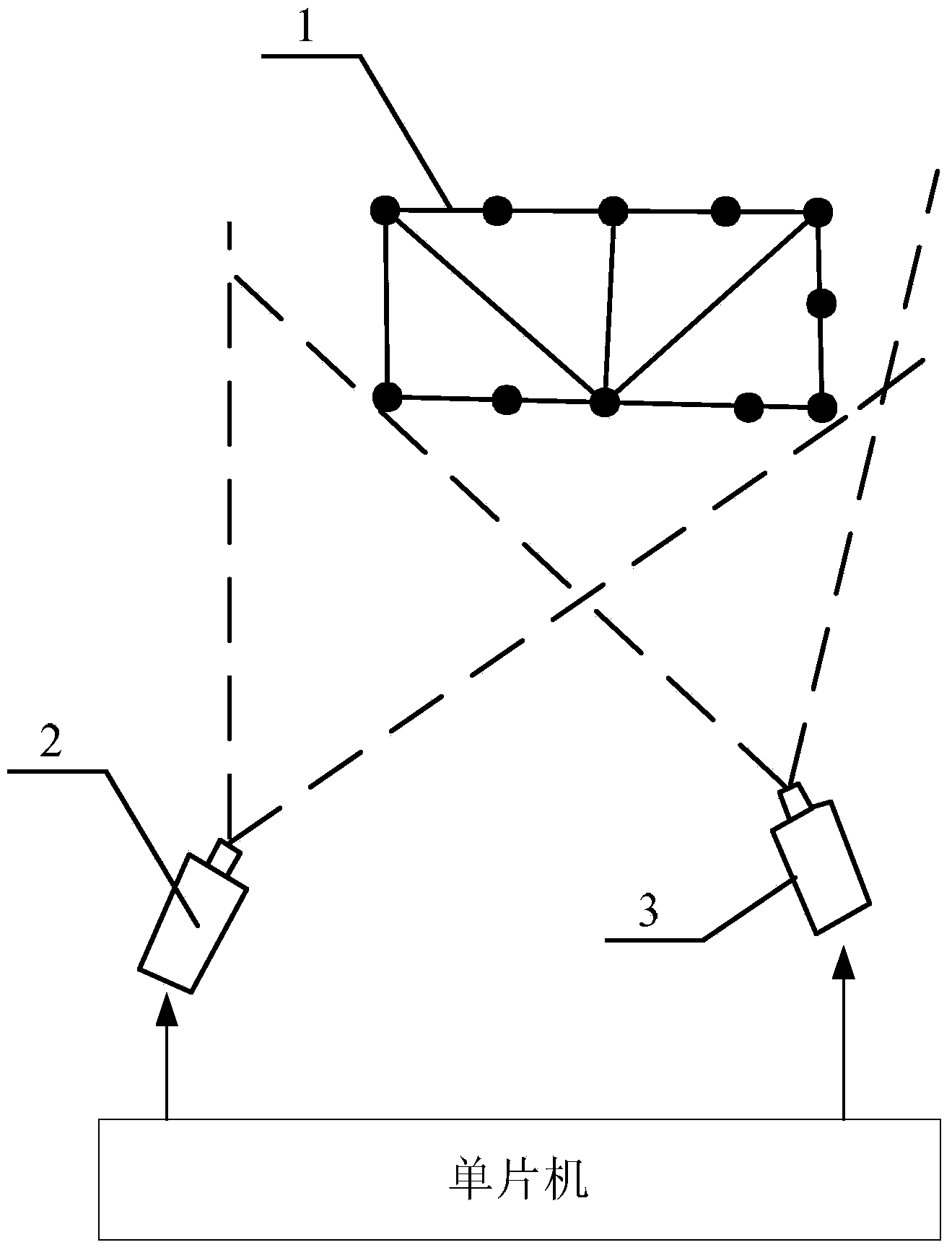
[0039] Specific implementation mode one: the following combination Figure 1 to Figure 3 Describe this embodiment, the binocular photogrammetry method of vibration displacement of large flexible structure described in this embodiment, it comprises the following steps:

[0040] Step 1: Calibrate the industrial camera, the number of the industrial camera is 2-5;

[0041]Step 2: Excite the flexible structure under test, and at the same time, control all industrial cameras to trigger synchronously through the single-chip microcomputer, and shoot the vibration displacement of the measured point of the flexible structure under test;

[0042] Step 3: Process the images captured by all industrial cameras, use the corner detection algorithm to obtain the pixel coordinates of the measuring point, and then use the binocular 3D reconstruction technology to obtain the object space coordinates of the measuring point at each moment, so as to obtain the measured flexible The vibration displa...

specific Embodiment approach 2

[0044] Specific implementation mode two: the following combination figure 1 This embodiment will be described. This embodiment will further explain Embodiment 1. The specific method for calibrating an industrial camera in this embodiment is:

[0045] The calibration board is used to calibrate the industrial camera. The calibration board is a 7×9 checkerboard consisting of black and white squares, and the side length of the square is 5mm; the position of the calibration board is set so that the field of view of each industrial camera covers Complete the calibration board, and take a still image of the calibration board with an industrial camera to complete the calibration.

[0046] The calibration plate in this embodiment is printed with a high-precision printer to ensure that the calibration accuracy of the industrial camera meets the measurement requirements. After the calibration is completed, the installation position and angle of the industrial camera and the focal length...

specific Embodiment approach 3

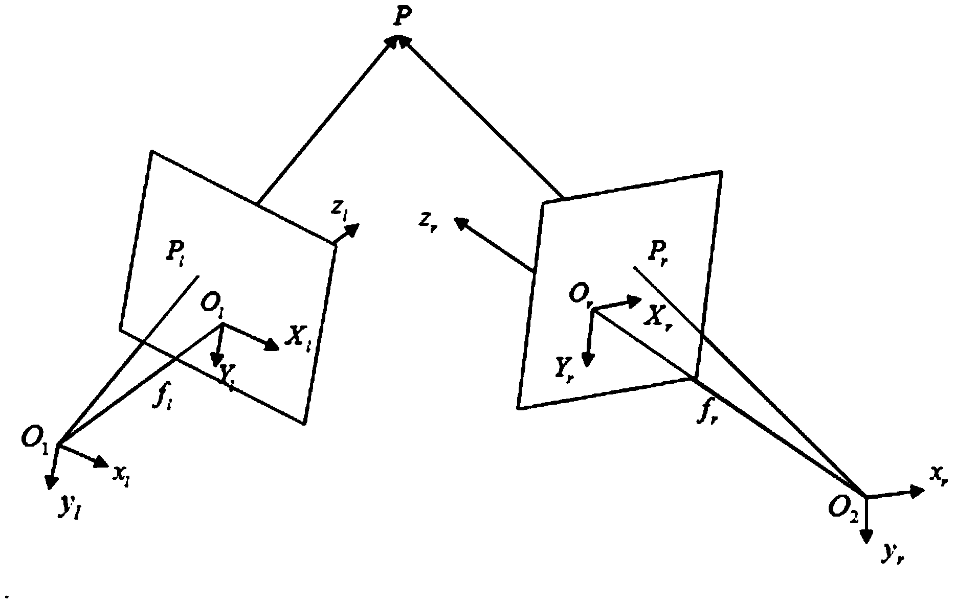
[0048] Specific implementation mode three: the following combination figure 2 and image 3 Describe this embodiment, this embodiment will further explain Embodiment 2, the number of industrial cameras described in this embodiment is 2, the specific method of obtaining the vibration displacement curve of the flexible structure under test in step 3 is:

[0049] The measured points of the flexible structure to be tested are photographed by two industrial cameras at the same time. After processing the captured images, the equations are established as follows:

[0050] Z c 1 u 1 v 1 ...


PUM


Abstract

The invention provides a binocular photogrammetry method of large flexible structure vibration displacement, and belongs to the technical field of flexible structure dynamic analysis and measurement. The binocular photogrammetry method of large flexible structure vibration displacement aims to solve the problem that the existing contact measurement impacts performance of a flexible structure. Firstly, industrial cameras are demarcated; then, shock excitation is conducted on the flexible structure to be tested, all the industrial cameras are controlled to be triggered synchronously through a single-chip microcomputer, and shooting of vibration displacement is conducted on the point to be tested of the flexible structure to be tested; next, images obtained by shooting of all the industrial cameras are dealt with, pixel coordinates of the point to be tested are obtained through an angular point detection algorithm, object space coordinates of the point to be tested at each point of time are obtained through a binocular three-dimensional reconstruction technology, and thus the vibration displacement curve of the flexible structure to be tested is obtained. The binocular photogrammetry method of large flexible structure vibration displacement is applied to measuring vibration displacement of the flexible structure.

Description

technical field [0001] The invention relates to a binocular photogrammetry method for vibration displacement of a large flexible structure, and belongs to the technical field of dynamic analysis and measurement of flexible structures. Background technique [0002] The application of binocular camera measurement mainly includes the high-precision detection of the three-dimensional shape of the car, the deformation of the structure in the wind tunnel experiment, the precision measurement of the large antenna surface, and the terrain surveying and mapping. Most of the camera 3D reconstruction techniques used in these measurements are used for 3D feature measurement of static objects, but cannot measure the vibration of objects. For the vibration of the flexible structure, the traditional contact measurement method of the acceleration sensor will not only affect the dynamic performance of the flexible structure, but also cause the error to be difficult to control and the noise t...

Claims


Application Information

Patent Timeline
IPC IPC(8): G01B11/03G01H11/00G01C11/08
Inventor 王聪许畅高晶波张春芳
Owner HARBIN INST OF TECH
Why Eureka
Try Eureka