
Charging roller capable of uniformly charging

A charging roller and uniform technology, applied in the direction of corona discharge devices, circuits, electrical components, etc., can solve the problems of smaller diameter of sponge layer 03, poor periodic image, larger diameter of sponge layer 03, etc.

Inactive Publication Date: 2014-07-30
佛山市埃申特科技有限公司
View PDF6 Cites 2 Cited by
  • Summary
  • Abstract
  • Description
  • Claims
  • Application Information

AI Technical Summary

Problems solved by technology

[0007] In all the above steps, the charging roller charges the surface of the photosensitive drum at a voltage of 500V ~ 1000V. As the first step in the printing process, the charging effect directly affects the execution quality of all subsequent steps and the final printing quality. In order to avoid If the charging roller charges the photosensitive drum unevenly, it is necessary to ensure that the surface of the charging roller has a uniform charge. , there will be printing defects in the blind spots, and there will be periodic poor image problems when printing
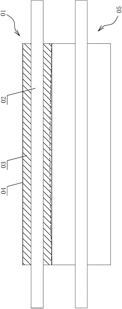
[0008] The surface of the currently commonly used charging roller 01 is an axially linear structure, such as figure 1 As shown, it is composed of a mandrel 02, an elastic sponge layer 03 and a conductive surface layer 04. When the sponge layer 03 is put on, it is easy to produce knob wrinkles. In addition, because the sponge is elastic, workers sometimes stretch it when putting on it, resulting in The diameter of the sponge layer 03 becomes smaller. If the length is shortened, the diameter of the sponge layer 03 will become larger
When rotating against the photosensitive drum 05, such as figure 2 As shown, since the photosensitive drum 05 is also an axially linear structure, after the surfaces of the two rollers are pressed against each other, affected by the strength of the charging roller 01, the two ends can ensure sufficient contact, but the middle part will appear concave, as shown in figure 2 For the effect shown by the dotted line in the middle, it is difficult to ensure that the entire roller body is fully in contact with the pressure. In some places, there will be no contact or insufficient contact, resulting in the charging roller 01 not being able to charge the photosensitive drum 05 or charging insufficiently. Sufficient, it will directly affect the quality of the subsequent electrostatic latent image, developing and fixing quality, and affect the overall printing quality of the printer

Method used


Image

  • Charging roller capable of uniformly charging
  • Charging roller capable of uniformly charging
  • Charging roller capable of uniformly charging

Examples


Embodiment Construction

[0020] The best mode for carrying out the present invention will be described below with reference to the accompanying drawings.

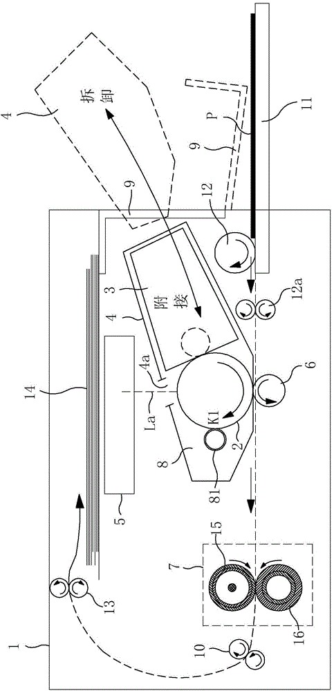
[0021] image 3 is a schematic sectional view showing a schematic configuration of a laser beam printer (hereinafter simply referred to as "printer") 1 as an image forming apparatus according to this embodiment.

[0022] The printer 1 receives image information from an image information providing device (not shown) such as a host computer provided outside the printer 1. The printer 1 executes a process for recording images in sheet form based on the received image information through a known electrophotographic system. A series of image forming processes for forming an image on a recording material (recording medium) P.

[0023] The laser beam printer 1 includes a process cartridge 4 housing a drum-shaped rotatable electrophotographic photosensitive drum 2 serving as a latent image bearing member, a charging mechanism 8 and a developing device 3 ....


PUM


Abstract

The invention discloses a charging roller capable of uniformly charging. The charging roller comprises a spindle, a sponge layer and a conductive surface layer, wherein the sponge layer coats the spindle; the conductive surface layer covers the sponge layer; and more than one deformation-resisting ring for resisting radial deformation of the sponge layer is distributed at the middle section of the spindle. Due to the adoption of the technical scheme, the deformation-resisting rings are increased at the middle section of the spindle, when the charging roller is pressed against a photosensitive drum, the middle section and the photosensitive drum are not fully contacted due to the middle section deformation, then the deformation-resisting rings are outwards supported in the radial direction due to the existence of the deformation-resisting rings, and deformation of the sponge layer is blocked. Meanwhile, the deformation of the middle section of the sponge layer is compensated, the middle section is driven to be fully contacted with the photosensitive drum, full contact between the charging roller and each part of the surface of the photosensitive drum is effectively guaranteed, the surface of the photosensitive drum is fully, effectively and uniformly charged by the charging roller, and the charging quality of the photosensitive drum is improved.

Description

Technical field: [0001] The invention relates to a charging roller with uniform charging. Background technique: [0002] Generally, in an image forming apparatus using toner using electrostatic electrophotography such as a copying machine, a facsimile machine, a printer, etc., the toner is supplied to a developing device through a toner supplying device including a toner cartridge or the like to be continuously processed. Image printing. [0003] The imaging process of such an imaging device generally includes the following steps: charging, exposure, development, transfer, separation, cleaning, charge removal, and fixing. [0004] More specifically, in the image forming process, the surface of the photosensitive drum, which is rotationally driven, is uniformly charged by the charging roller (charging step). The surface of the photosensitive drum thus charged is irradiated with a laser beam of an exposure device to form an electrostatic latent image (exposure step). Subseq...

Claims


Application Information

Patent Timeline
Patent Type & Authority Applications(China)
IPC IPC(8): G03G15/02
Inventor 刘江
Owner 佛山市埃申特科技有限公司
Learn More