Direct charge type electrical vehicle safety charge station/pile

A technology for electric vehicles and charging stations, which is applied in the direction of electric vehicle charging technology, charging stations, electric vehicles, etc., can solve the problems of shortening the service life of batteries, difficulties in popularizing charging stations, and damage to battery performance life, so as to improve performance and use Longevity, reduction of economic and usage burden, promotion of safety in use

Active Publication Date: 2015-05-06
郑州伏特电子科技有限公司
View PDF4 Cites 1 Cited by
  • Summary
  • Abstract
  • Description
  • Claims
  • Application Information

AI Technical Summary

Problems solved by technology

[0005] 1. Due to the supply of 220V AC power supply, there are hidden dangers to the personal safety of the charging operator, which increases the difficulty and operational requirements of the charging operation
2. Users still use their own chargers, but the quality and performance of users' chargers are uneven, and most of them are inferior chargers. Accidents such as fires caused by chargers occur from time to time; charging also has a great impact on the performance and life of the battery. Great damage, significantly shorten the service life of the battery
3. Since the card swiping control box is far away from the electric vehicle, it is inconvenient for the user to swipe the card
4. The charging station of this structure does not have the function of rainproof and waterproof, that is, it can only be installed indoors. According to the national conditions, it is not realistic to let all electric vehicles be parked and charged indoors, so it is difficult to popularize this type of charging station.
5. The structure of the charging station still adopts the wiring form of AC power supply, which is insufficient in aesthetics

Method used


Image

  • Direct charge type electrical vehicle safety charge station/pile
  • Direct charge type electrical vehicle safety charge station/pile
  • Direct charge type electrical vehicle safety charge station/pile

Examples


Embodiment 1

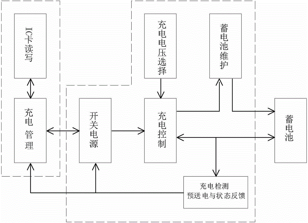
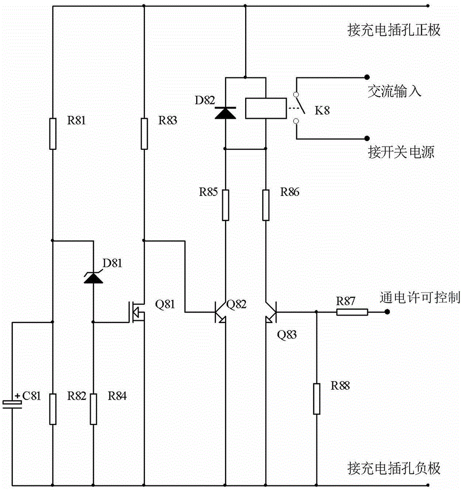
[0029] see figure 1 , figure 2 , the direct charging electric vehicle safety charging pile in this embodiment includes a pile structure, an AC power supply unit, a charging component, and a charging management component. The AC power supply unit is each charging component and a charging The management component provides power, and the charging jacks or plugs connected to the batteries of electric vehicles are drawn from the charging components. The charging jacks or plugs connected to the charging components are equipped with a pre-power transmission control circuit. The control circuit is composed of a field effect transistor Q81, a transistor Q82, a transistor Q83 and their respective peripheral components; the drain of the field effect transistor Q81 and the emitters of the transistors Q82 and Q83 are connected to the negative pole of the charging jack or the plug lead-out terminal, and the field effect transistor The source of Q81 is connected to the positive pole of the...

Embodiment 2

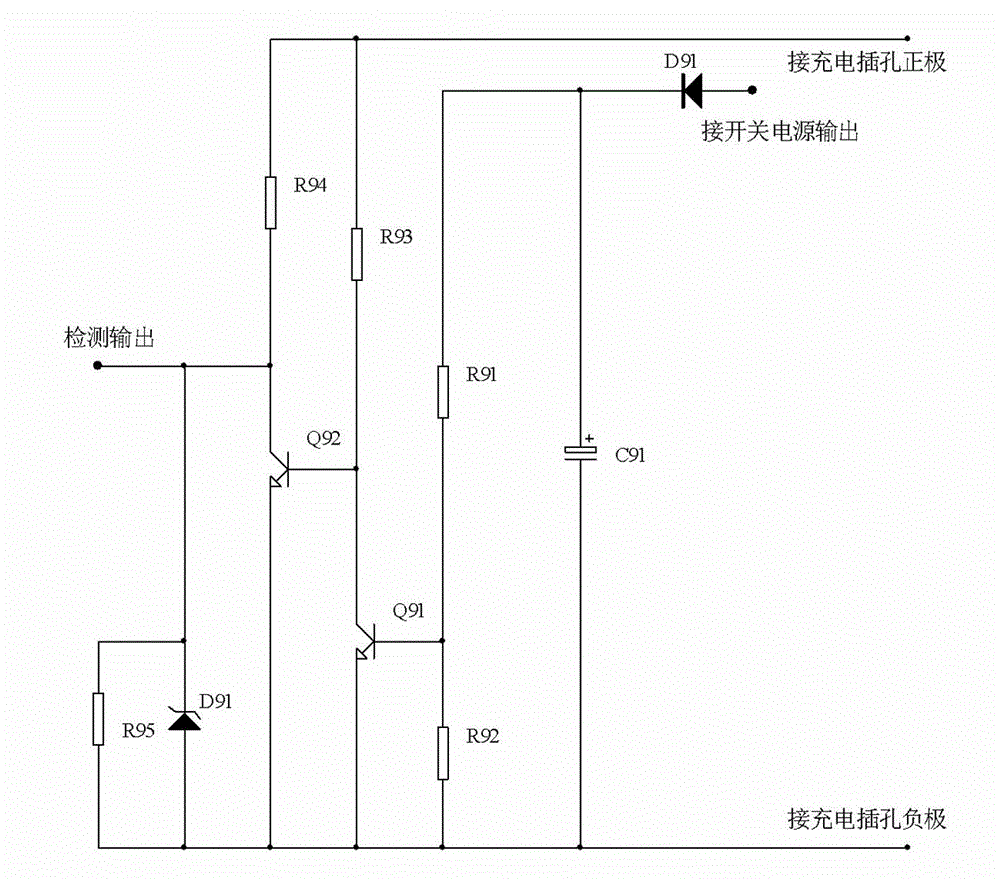
[0038] see figure 1 , figure 2 , image 3 The difference between the direct-charging electric vehicle safety charging pile of this embodiment and Embodiment 1 is that a charging permission circuit is provided in conjunction with each charging component, and the charging component charging permission circuit is composed of a battery and a corresponding charging component. The switching power supply forms an "AND" relationship, and the charging management component can only work when both have output (that is, when the state is normal); the charging permission circuit is composed of two inverters Q91, Q92 and their peripheral components, and the inverter The phasers Q91 and Q92 are powered by batteries, the control terminal of the inverter Q91 is connected to the output terminal of the switching power supply of the charging assembly, the output terminal of the inverter Q91 is connected to the input terminal of the inverter Q92, and the output terminal of the inverter Q92 is T...

Embodiment 3

[0046] see Figure 1 ~ Figure 4 The difference between the direct charging electric vehicle safety charging pile of this embodiment and Embodiment 1 or Embodiment 2 is that the AC power supply unit consists of an AC contactor k51 and a control relay k52 to form an interlock control circuit, and the AC contactor The input and output terminals of the two sets of contacts of the contactor are respectively connected to the incoming and outgoing lines of the AC power supply. The driving coil of the AC contactor is connected to the AC power supply through the contacts of the control relay to form a loop. The driving coil of the control relay is connected to the battery of the electric vehicle under control. ; One end of the charging jack or plug of each charging component is connected to a node through a diode, and the driving coil of the control relay is connected to the node and the negative pole of the charging jack or plug of the charging component.

[0047] Design ideas: AC pow...


PUM


Abstract

The invention discloses a direct charge type electrical vehicle safety charge station / pile comprising an alternate power supply unit, charge components, a charge management component, a charging socket or plug connected with the charge components and a previous power transmission control circuit which is arranged at the guiding end of the charging socket or plug and which is composed of a field effect transistor Q81, transistors Q82 and Q83 and peripheral components. The drain electrode of the field effect transistor and the emission electrodes of the transistors are connected to the charging socket or negative electrode of the plug, the source electrode of the field effect transistor Q81 is connected to the charging socket or negative electrode of the plug, the source electrode output end of the field effect transistor Q81 is connected to the base electrode of the transistor Q82, the grid electrode of the field effect transistor Q81 is connected to a voltage sampling circuit through a voltage stabilizing tube, the collecting electrodes of the transistors Q82 and Q83 are connected to the charging socket or negative electrode of the plug through a control relay, one switch contact end of the control relay is connected to an alternate current input, and one end is connected to one switch power supply input ends of the charging components; a charge switching on-off control circuit is formed through the transistor Q83 and the peripheral components; the base electrode of the transistor Q83 is connected to a switch-on admission control signal output end of the charge management component.

Description

technical field [0001] The invention relates to an electric vehicle charging station / pile, in particular to an electrical structure of a direct charging type electric vehicle safe charging station / pile. Background technique [0002] Electric vehicles are popularized rapidly due to the advantages of low purchase price, small size, easy storage, simple operation, convenient use and low cost of use. In order to facilitate the charging of electric vehicles and standardize the charging environment, the charging station came into being. At present, the structure of the widely popular charging station is as follows: the management system consisting of card swiping or coin-operated charging components and charging timing components is installed in a box, and the control box Lead out the power supply wire. The power supply wire is pasted on the wall in the same way as the household AC power supply and extends forward. Install a power socket at a certain distance. When the user needs ...

Claims


Application Information

Patent Timeline
IPC IPC(8): H02J7/00
CPCB60L53/31B60L53/665Y02T10/70Y02T10/7072Y02T90/12
Inventor 徐俊亚
Owner 郑州伏特电子科技有限公司
Why Eureka
Try Eureka