Method for predicating residual intensity of metal gradient material with cracks

A gradient material and strength prediction technology, which is applied in special data processing applications, instruments, electrical digital data processing, etc., can solve the problems of large cumulative errors and high calculation costs, and achieve the effect of residual strength prediction

Inactive Publication Date: 2014-07-30
NANJING UNIV OF AERONAUTICS & ASTRONAUTICS
View PDF1 Cites 18 Cited by
  • Summary
  • Abstract
  • Description
  • Claims
  • Application Information

AI Technical Summary

Problems solved by technology

[0009] The present invention overcomes the defects of excessive calculation cost and large cumulative error caused by subdividing the grid of the finite element model in the prior art, and adopts the discontinuous displacement interpolation function of the extended uni

Method used


Image

  • Method for predicating residual intensity of metal gradient material with cracks
  • Method for predicating residual intensity of metal gradient material with cracks
  • Method for predicating residual intensity of metal gradient material with cracks

Examples


Example Embodiment

[0080] Example

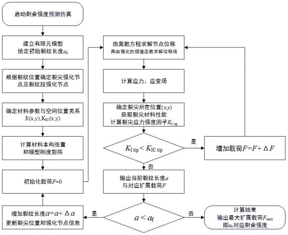
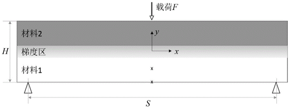
[0081] Step 1. Establish a finite element model such as image 3 , the height of the model is H=24mm, the material gradient area is located at a highly symmetrical place, its thickness is t=1mm, and the span between fulcrums is S=96mm. This embodiment deals with edge cracks, so there is only one crack tip, and the places marked with x are the crack tip and the crack start point respectively, the crack start point is located at the middle point of the lower boundary of the model, and the distance between the crack tip and the start point is the initial crack length a 0 =8.6mm, define the crack termination length a in this embodiment f =15mm.

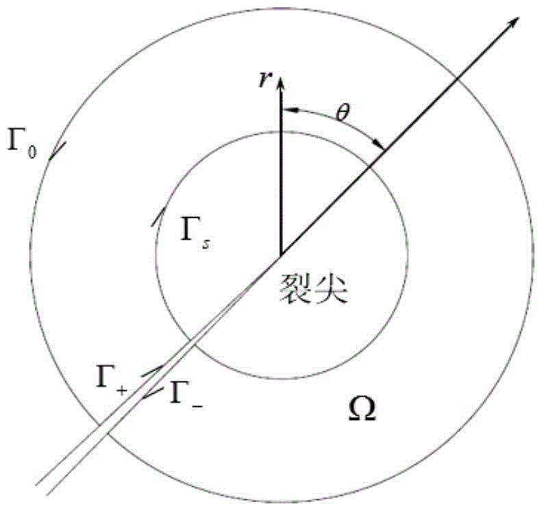
[0082] Step 2. Use rectangular units to discretize the model, the grid side length is 1mm, a total of 2640 units; processing node enhancement information such as Figure 4 , the element nodes related to the crack tip are included in the crack tip strengthening node set N Λ , the element nodes related to the crack segm...


PUM


Abstract

The invention discloses a method for predicating the residual intensity of a metal gradient material with cracks. According to the method, a finite element model is utilized, discontinuous displacement interpolation functions of an expansion unit are adopted for characterizing crack behaviors in the model, the crack length is taken as a variable to track crack tip positions so as to dynamically judge stress intensity factors of crack tips and the fracture toughness size corresponding to the crack tips, so that whether cracks are expanded are determined, and predication on the residual intensity of the gradient material is realized. The method has the advantages that geometrical cutting is not needed during the establishment of the finite element model, a crack tip grid is not needed to be subdivided, and the precision is higher.

Description

technical field [0001] The invention belongs to the simulation simulation of the mechanical properties of metal gradient materials, and more specifically relates to a method for predicting the residual strength of metal gradient materials containing cracks. Background technique [0002] Metal gradient material is a new type of composite material system with the development of modern additive manufacturing (3D printing) technology, referring to the design concept of functional gradient material to change material components to achieve specific functions, and the content of different metal components obtained by processing changes along a specific direction . This material not only retains the characteristics of traditional metal materials but is still suitable for structural load-bearing parts, and at the same time reduces the weak link caused by the mechanical connection between components, and can achieve specific functions according to design requirements like functionally...

Claims


Application Information

Patent Timeline
IPC IPC(8): G06F19/00
Inventor 许希武赵震波郭树祥陈康
Owner NANJING UNIV OF AERONAUTICS & ASTRONAUTICS
Why Eureka
Try Eureka