Multi-station discharge micropore machining equipment and machining method thereof

A micro-hole processing and multi-station technology, applied in the field of machining, can solve the problems of difficult processing, sagging of micro-holes, and many defective products, and achieve the effect of non-sagging and uniform hole edges, improving uniformity, and avoiding sagging

Active Publication Date: 2014-08-06
TAICANG DELTA PRECISION TOOLS
View PDF6 Cites 6 Cited by
  • Summary
  • Abstract
  • Description
  • Claims
  • Application Information

AI Technical Summary

Problems solved by technology

[0002] At present, in the field of machining, it is very difficult to process multi-station micro-holes with slopes, especially micro-holes with a diameter of less than 1 mm, which cannot guarantee the machining accuracy of micro-holes; if the existing equipment is used for processing , even if the micro-hole processing action with a diameter of less than 1mm is completed, various problems such as drooping or unevenness will occur on the edge of the micro-hole, resulting in many defective products and a high rejection rate; this is mainly due to the discharge micro-hole processing of extremely small micro-hole The motor of the processing equipment is small, and it will be caused by slight deformation during the discharge process, especially the bottom end of the electrode is prone to forward tilt or vibration.

Method used


Image

  • Multi-station discharge micropore machining equipment and machining method thereof
  • Multi-station discharge micropore machining equipment and machining method thereof
  • Multi-station discharge micropore machining equipment and machining method thereof

Examples


Embodiment Construction

[0022] Below in conjunction with accompanying drawing and specific embodiment, further illustrate the present invention, should understand that following specific embodiment is only for illustrating the present invention and is not intended to limit the scope of the present invention, after having read the present invention, those skilled in the art will understand the present invention Modifications of various equivalent forms fall within the scope defined by the claims of the present application.

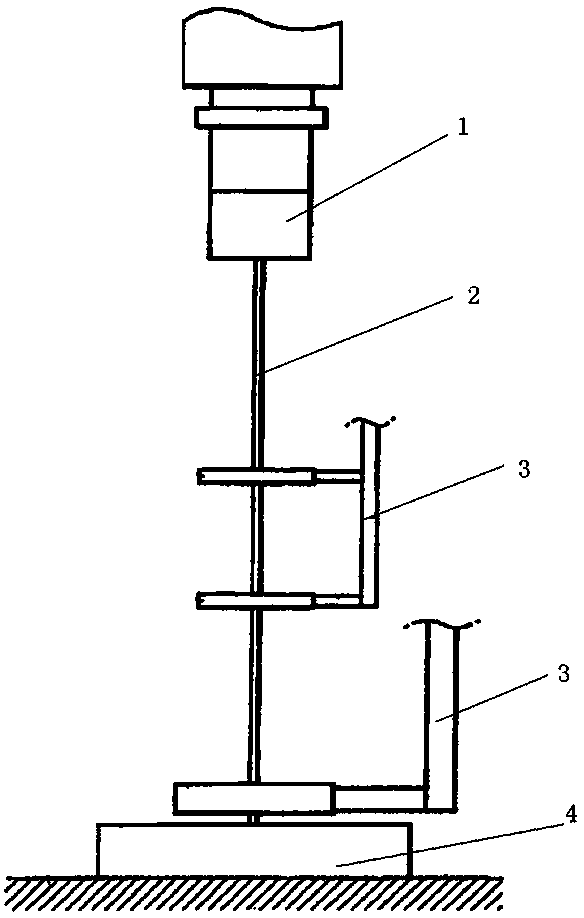
[0023] As shown in the figure, a multi-station electric discharge microhole processing equipment includes: electric discharge machine 1, motor 2, guide 3 and base 4 (such as figure 1 ); there are three guides in this embodiment, an upper guide, a middle guide and a lower guide; the base 4 is a rotating base.

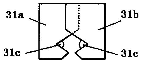
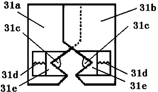
[0024] In the present embodiment, the structure of the upper guide and the middle guide is as follows (as figure 2 ): including: left clamp 31a, right clamp 31b and insula...


PUM

PropertyMeasurementUnit
angleaaaaaaaaaa

Abstract

The invention discloses multi-station discharge micropore machining equipment which comprises an electric discharge machine, a motor, guiders and a base. A guider chuck in each guider comprises a left chuck body, and a right chuck body and insulation elastic blocks. V-shaped grooves with transverse openings are formed in the inner sides of the left chuck bodies and the inner sides of the right chuck bodies, and the angles of the openings of the V-shaped grooves range from 30 degrees to 45 degrees. The openings of the V-shaped grooves in the inner sides of the left chuck bodies are opposite to the openings of the V-shaped grooves in the inner sides of the right chuck bodies, and the insulation elastic blocks are arranged at the bottom ends of the inner sides of the V-shaped grooves. According to the multi-station discharge micropore machining equipment, due to the fact that the inner sides of the left chuck bodies and the inner sides of the right chuck bodies are designed into the V-shaped grooves, the left chuck bodies and the right chuck bodies are closed to clamp an electrode in the using process, and the electrode is fixed effectively; furthermore, the insulation elastic blocks are arranged at the bottom ends of the inner sides of the V-shaped grooves, when the electrode is deformed or slightly vibrated in the discharge process, the deformation and the slight vibration of the electrode are reduced by arranging the insulation elastic blocks, and thus the precision of machined micropores is improved.

Description

technical field [0001] The invention relates to a multi-station electric discharge microhole processing equipment and method, belonging to the technical field of machining. Background technique [0002] At present, in the field of machining, it is very difficult to process multi-station micro-holes with slopes, especially micro-holes with a diameter of less than 1 mm, which cannot guarantee the machining accuracy of micro-holes; if the existing equipment is used for processing , even if the micro-hole processing action with a diameter of less than 1mm is completed, various problems such as drooping or unevenness will occur on the edge of the micro-hole, resulting in many defective products and a high rejection rate; this is mainly due to the discharge micro-hole processing of extremely small micro-hole The motor of the processing equipment is small, which will be caused by micro deformation during the discharge process, especially the lowermost end of the electrode is prone ...

Claims


Application Information

Patent Timeline
Patent Type & Authority Applications(China)
IPC IPC(8): B23H1/00B23H7/26
Inventor 陈显贵
Owner TAICANG DELTA PRECISION TOOLS
Why Eureka
Try Eureka