
High-precision passenger tire molding machine adopting two-time method

A molding machine and secondary method technology, applied in tires, applications, household appliances, etc., can solve the problems of asynchrony of cylinders, small radial stroke, poor repeatability, etc., and achieve good coaxiality, good repeatability, and alignment. good effect

Inactive Publication Date: 2014-08-06
WUHU DERY ENG
View PDF5 Cites 7 Cited by
  • Summary
  • Abstract
  • Description
  • Claims
  • Application Information

AI Technical Summary

Problems solved by technology

[0003] The one-stage forming machine in the prior art includes a main shaft assembly for installing a one-stage forming drum. The main shaft assembly includes an outer shaft and an inner shaft protruding from the outer shaft and connected with a one-stage forming drum. The one-stage forming machine is fixed by the outer shaft And the axial movement of the inner shaft produces the contraction and expansion of a section of the forming drum to form the carcass. The main shaft assembly of this structure occupies a large space, and the radial stroke of the main shaft assembly driving a section of the forming drum is small, which affects the forming effect of the carcass and efficiency
[0004] The two-stage molding machine in the prior art includes a transfer ring for transporting the tire crown to the carcass. The transfer ring uses multiple cylinders to drive the clamping blocks synchronously to clamp the tire crown. The problem of asynchrony leads to poor alignment and poor repeatability of the transfer ring. The crown position of each transfer cannot be guaranteed to be consistent, which easily affects the quality of the green tire and leads to poor coaxiality of the green tire structure.

Method used


Image

  • High-precision passenger tire molding machine adopting two-time method
  • High-precision passenger tire molding machine adopting two-time method
  • High-precision passenger tire molding machine adopting two-time method

Examples


Embodiment Construction

[0036] The specific embodiment of the present invention will be described in further detail by describing the embodiments below with reference to the accompanying drawings, the purpose is to help those skilled in the art to have a more complete, accurate and in-depth understanding of the concept and technical solutions of the present invention, and contribute to its implementation.

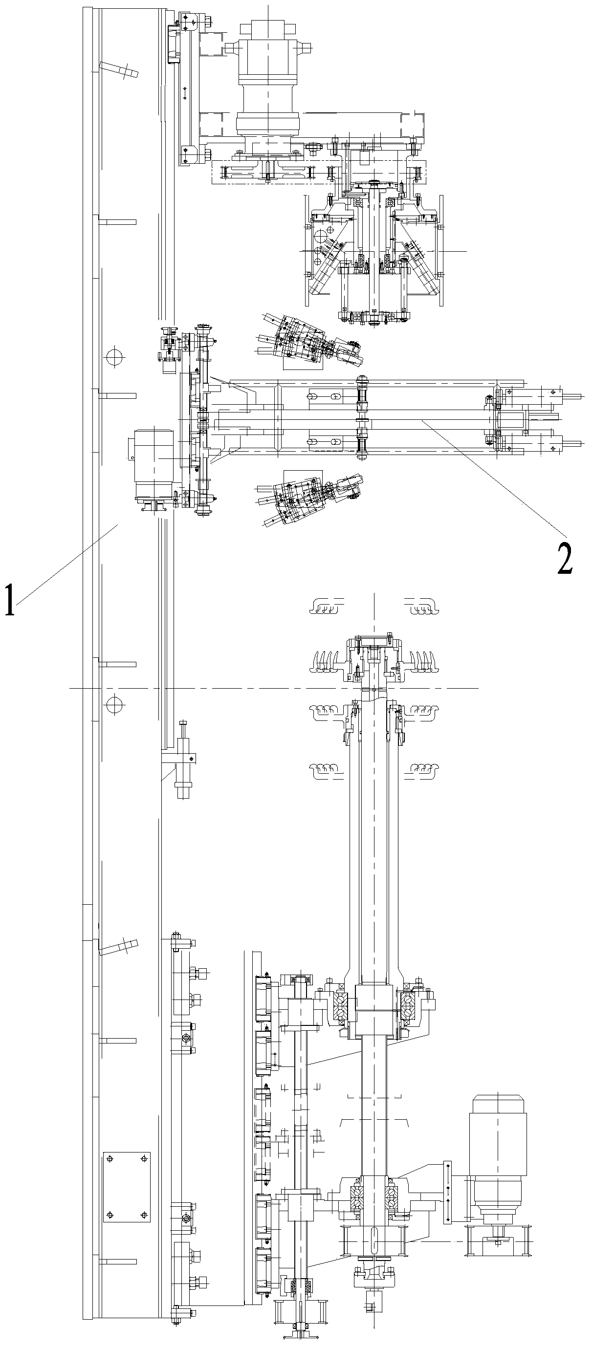
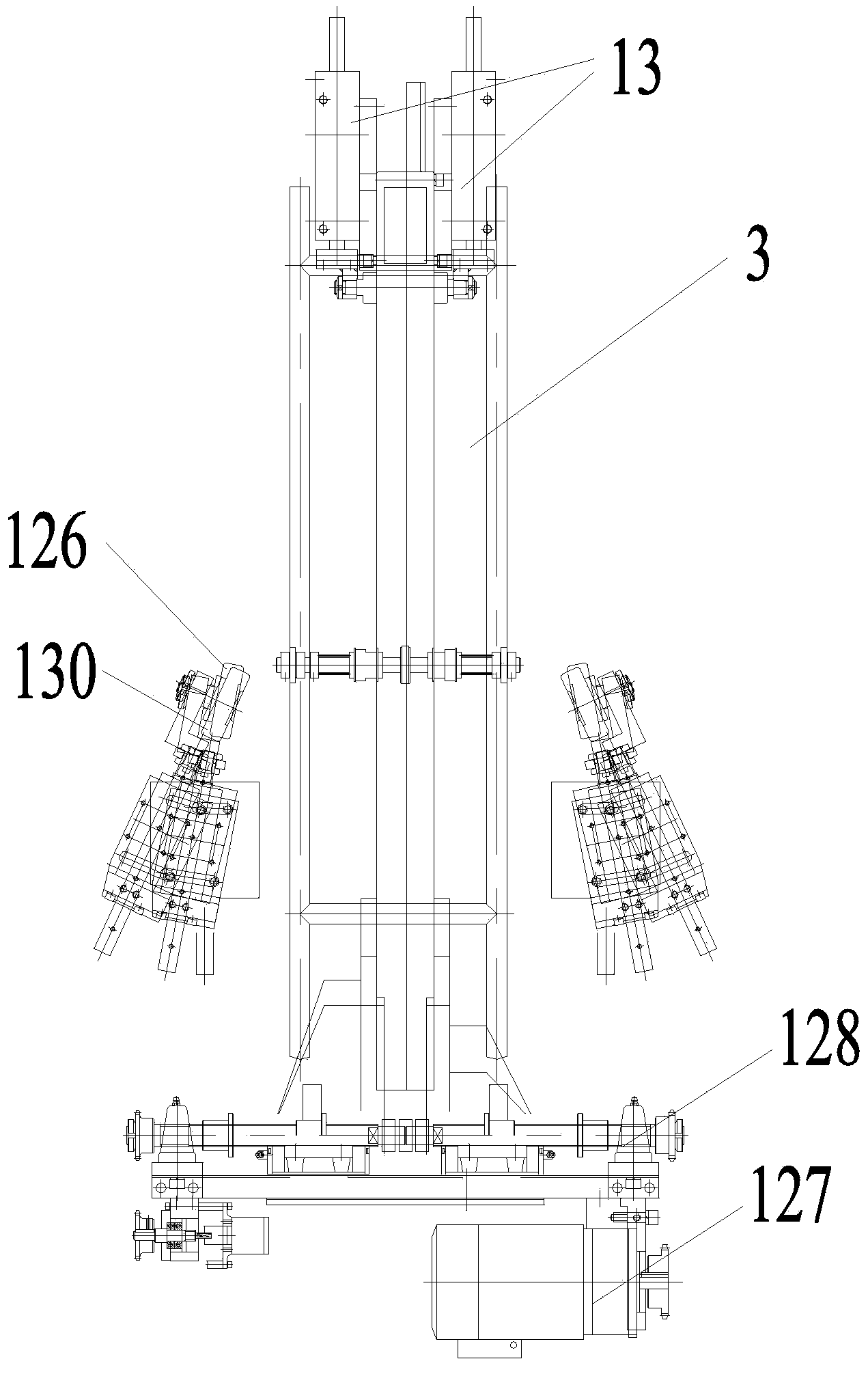
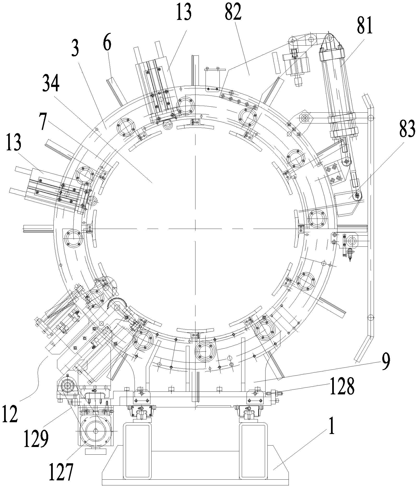
[0037] Such as Figure 1 to Figure 16 As shown, a high-precision passenger tire secondary molding machine includes a one-stage molding machine for making a carcass and a two-stage molding machine for making a tire crown and combining the tire crown and the carcass to form a green tire. The forming machine includes a section of base 14 and a main shaft assembly 15. A section of forming drum 10 is installed on the main shaft assembly 15. The second section of forming machine includes a second section of base 1 and a transfer ring 2 for transporting the crown. The transfer ring 2 includes a second se...


PUM


Abstract

The invention discloses a high-precision passenger tire molding machine adopting a two-time method. The molding machine comprises a first section molding machine and a second section molding machine, wherein the second section molding machine comprises a second section base and a transferring ring; the transferring ring comprises a transferring base, a ring body and a clamping mechanism; a centre hole is formed in the centre of the ring body; the clamping mechanism comprises a plurality of clamping blocks; a rotary ring-shaped gear coaxial with the centre hole is arranged on the ring body, and is connected with the clamping blocks through a gear rack mechanism. According to the molding machine of the passenger tire, as the ring-shaped gear is arranged and is connected with the clamping blocks through the gear rack mechanism, and the gear rack mechanism converts rotary motion input by the ring-shaped gear into linear motion of the clamping blocks, synchronous motion of the clamping blocks can be realized to clamp and release a crown; the transferring ring adopting the structure is excellent in centering performance and repeatability; the position of the crown transferred each time can be ensured to be uniform and good in coaxiality of a tire blank. Therefore, the quality of the tire blank can be improved.

Description

technical field [0001] The invention relates to tire production equipment, in particular, the invention relates to a high-precision passenger tire secondary molding machine. Background technique [0002] The secondary forming machine used to produce passenger tire blanks is mainly composed of a one-stage forming machine and a two-stage forming machine. The one-stage forming machine is used to make the cord and inner liner The crown is made and compacted onto the carcass made by a one-stage molding machine to create the green tire, the green tire. [0003] The one-stage forming machine in the prior art includes a main shaft assembly for installing a one-stage forming drum. The main shaft assembly includes an outer shaft and an inner shaft protruding from the outer shaft and connected with a one-stage forming drum. The one-stage forming machine is fixed by the outer shaft And the axial movement of the inner shaft produces the contraction and expansion of a section of the form...

Claims


Application Information

Patent Timeline
Patent Type & Authority Applications(China)
IPC IPC(8): B29D30/26
Inventor 王文浩何孔年
Owner WUHU DERY ENG
Learn More