Supercharge Your Innovation With Domain-Expert AI Agents!

Air condition unit in vehicle

A technology for air conditioning units and cabins, applied in vehicle components, air handling equipment, heating/cooling equipment, etc., to solve problems such as abnormal working noise

Active Publication Date: 2014-08-06
DENSO CORP
View PDF6 Cites 0 Cited by
  • Summary
  • Abstract
  • Description
  • Claims
  • Application Information

AI Technical Summary

Problems solved by technology

As can be seen from the above, there is the following problem: With the conventional sliding door as in Patent Document 1, when the sliding door operates, abnormal operation noise is generated due to the unevenness on the surface of the film member.

Method used


Image

  • Air condition unit in vehicle
  • Air condition unit in vehicle
  • Air condition unit in vehicle

Examples


no. 1 approach

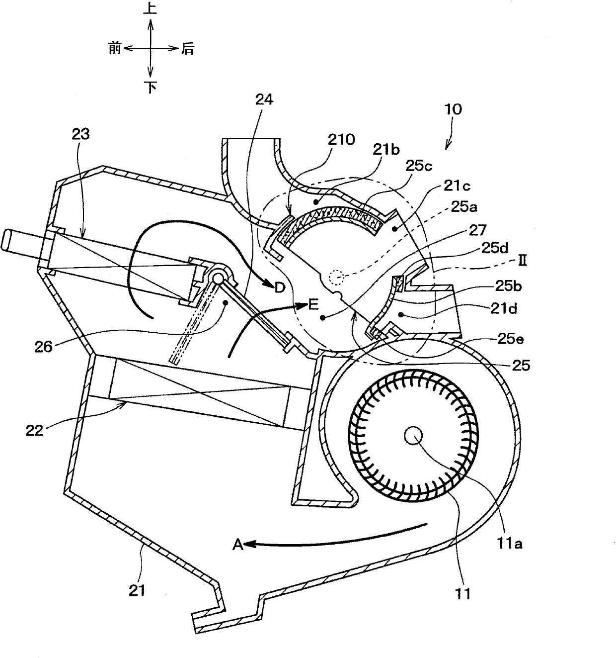
[0024] figure 1 The first embodiment of the interior air conditioning unit 10 of the present disclosure is shown. figure 1 A schematic configuration of the interior air-conditioning unit 10 is shown, and a cross-sectional view is shown in order to determine an air flow path in the interior air-conditioning unit 10 . exist figure 1 In FIG. 2 , the arrows in the up, down, front and back indicate the directions in which the interior air-conditioning unit 10 is mounted on the vehicle.

[0025] The interior air conditioning unit 10 is an air conditioning unit disposed in the interior of a vehicle, and constitutes a vehicle air conditioner together with, for example, a compressor and a cooler disposed in an engine room.

[0026] Such as figure 1 As shown, the interior air conditioning unit 10 includes, for example, a blower 11 that is a centrifugal blower. The blower 11 discharges the air taken in from the axial direction of the rotation shaft 11 a of the blower 11 radially outw...

no. 2 approach

[0077] Next, use Figure 7 , Figure 8 A second embodiment of the present disclosure will be described. Figure 7 It is a figure which shows the surface material 42 side of the 1st sealing material 25c of this embodiment, Figure 8 yes Figure 7 Sectional view of VIII-VIII. In this embodiment, differences from the first embodiment will be mainly described, and the description of the same or equivalent parts as the first embodiment will be omitted or simplified.

[0078] In this embodiment, if Figure 7 , Figure 8 As shown, at the skin member 42, the first rib 42a of the first embodiment is replaced with a first rib 52a. In addition, the second rib 42b of the first embodiment is replaced with a second rib 52b. That is, in the thickness direction of the skin member 42, the height of the first rib 52a is greater than that of the second rib 52b. On the other hand, the elastic packing member 40 is completely the same as that of the first embodiment. The 1st rib part 52a c...

no. 3 approach

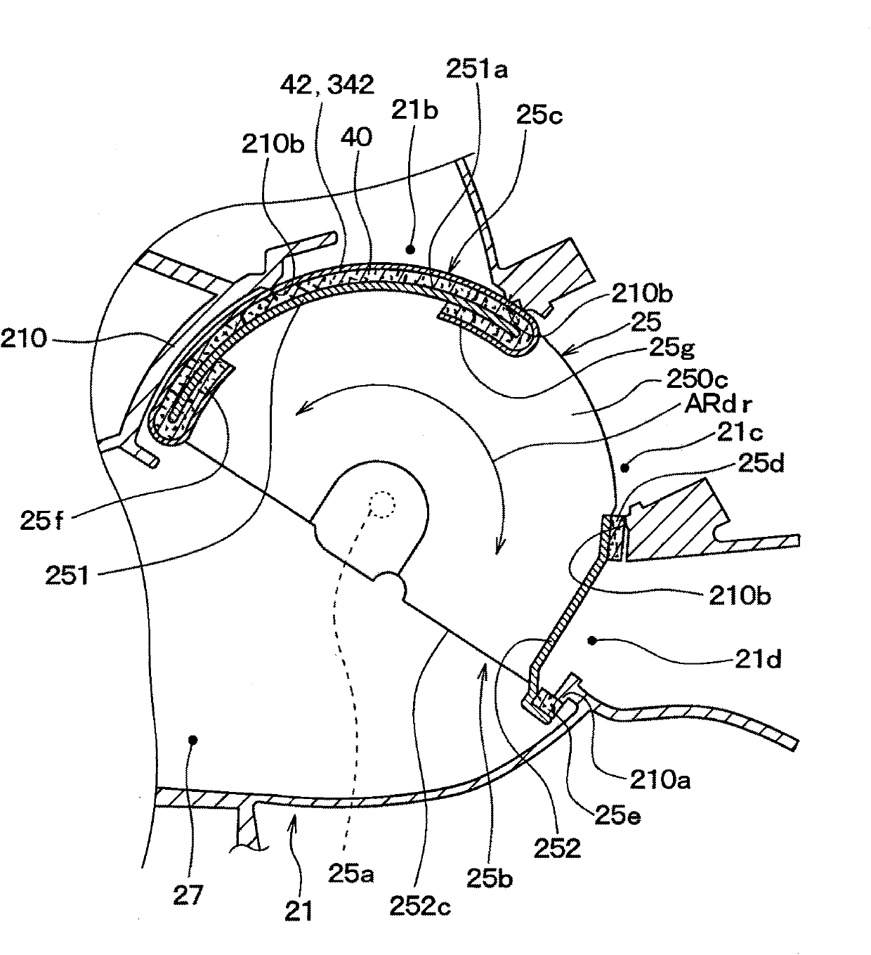
[0086] Next, use Figure 9 A third embodiment of the present disclosure will be described. Figure 9 It is a figure which shows the skin material 342 of this embodiment. in the Figure 9 Among them, the casing peripheral wall portion 210 of the skin member 342 is shown (refer to figure 2 )side. That is, in Figure 9 , the sliding surface of the skin 342 is shown. In this embodiment, differences from the first embodiment will be mainly described, and the description of the same or equivalent parts as the first embodiment will be omitted or simplified.

[0087] In this embodiment, at the first sealing member 25c, the skin member 342 is different from the first embodiment. Such as Figure 9 As shown, the skin material 342 of the present embodiment is constituted by a fabric material in which a plurality of first fibers 344 and second fibers 346 whose longitudinal directions are perpendicular to each other are woven. Figure 9 The skin member 342 is woven by a so-called t...


PUM


Abstract

The invention provides an air condition unit in a vehicle. A first seal member (25c) is provided with a plurality of first ribs (42s) extending along a sliding direction (ARdr) of a discharge mode door (25) as a sliding door in a long slip shape. The first seal member (25c), particularly the first seal member (42a) contact and slide in relative to circumferential wall portion of a shell in a press manner. When the discharge mode door (25) slides in relative to the circumferential wall portion of the shell, the first ribs (42s) mainly slide along the sliding direction (ARdr) and contact with the circumferential wall portion of the shell in a linear shape. Therefore, compared with a plane contact with the circumferential wall portion (210) of the shell without a surface member (42), the first seal member (25c) slides smoothly in relative to the circumferential wall portion (210) of the shell, thereby reducing working abnormal noise during the sliding process.

Description

technical field [0001] The present disclosure relates to an air-conditioning unit in a vehicle cabin provided with a sliding door for switching an air flow path. Background technique [0002] There is known an in-cabin air-conditioning unit in which an opening formed in a wall constituting an air-conditioning case is opened and closed by a sliding door that slides relative to the wall within the air-conditioning case. For example, the interior air conditioning unit disclosed in Patent Document 1 has the above-mentioned structure. In the cabin air-conditioning unit of Patent Document 1, the sliding door is a swing door that rotates about one axis and slides relative to the wall of the air-conditioning case. The swing door has a smooth film-shaped film part on the side facing the air-conditioning housing. Specifically, the film member is attached to a resin member serving as a skeleton of the swing door through partially provided urethane foam or the like. The revolving doo...

Claims


Application Information

Patent Timeline
Patent Type & Authority Applications(China)
IPC IPC(8): B60H1/00
Inventor 吉田隆弘佐藤康弘宫原贵文
Owner DENSO CORP
Features
  • R&D
  • Intellectual Property
  • Life Sciences
  • Materials
  • Tech Scout
  • Unparalleled Data Quality
  • Higher Quality Content
  • 60% Fewer Hallucinations
Learn More