Slitter machine unrolling fixing device and high-speed slitter machine

A technology of fixing device and slitting machine, which is applied in the direction of winding strips, transportation and packaging, thin material handling, etc. problems, to achieve the effect of reducing replacement, smooth operation and high versatility

Active Publication Date: 2014-08-06
SHENZHEN KUNHONG PRINTING
View PDF7 Cites 7 Cited by
  • Summary
  • Abstract
  • Description
  • Claims
  • Application Information

AI Technical Summary

Problems solved by technology

However, in actual production, it often occurs that the two ends of the paper tube core are deformed by the two chucks, causing the chucks to slip, resulting in unstable unwinding tension and affecting product quality. Cracking shortens the service life of the paper core, which undoubtedly increases the production cost

Method used


Image

  • Slitter machine unrolling fixing device and high-speed slitter machine
  • Slitter machine unrolling fixing device and high-speed slitter machine
  • Slitter machine unrolling fixing device and high-speed slitter machine

Examples


Embodiment Construction

[0021] It should be understood that the specific embodiments described here are only used to explain the present invention, not to limit the present invention.

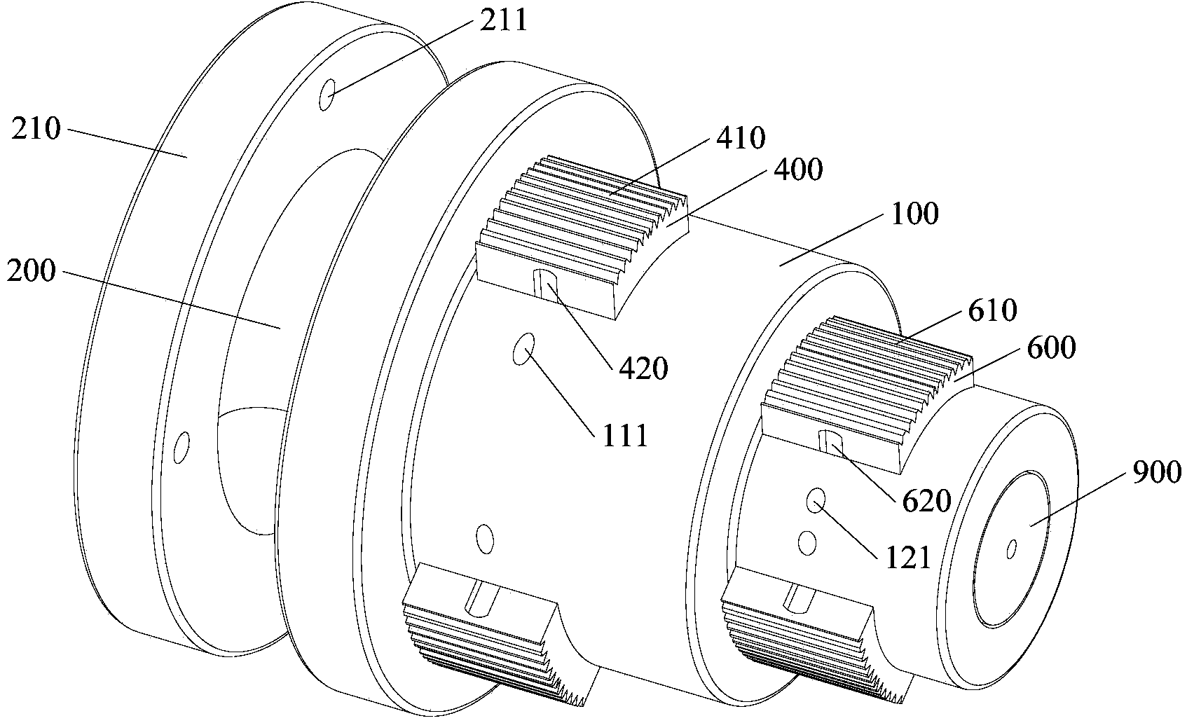
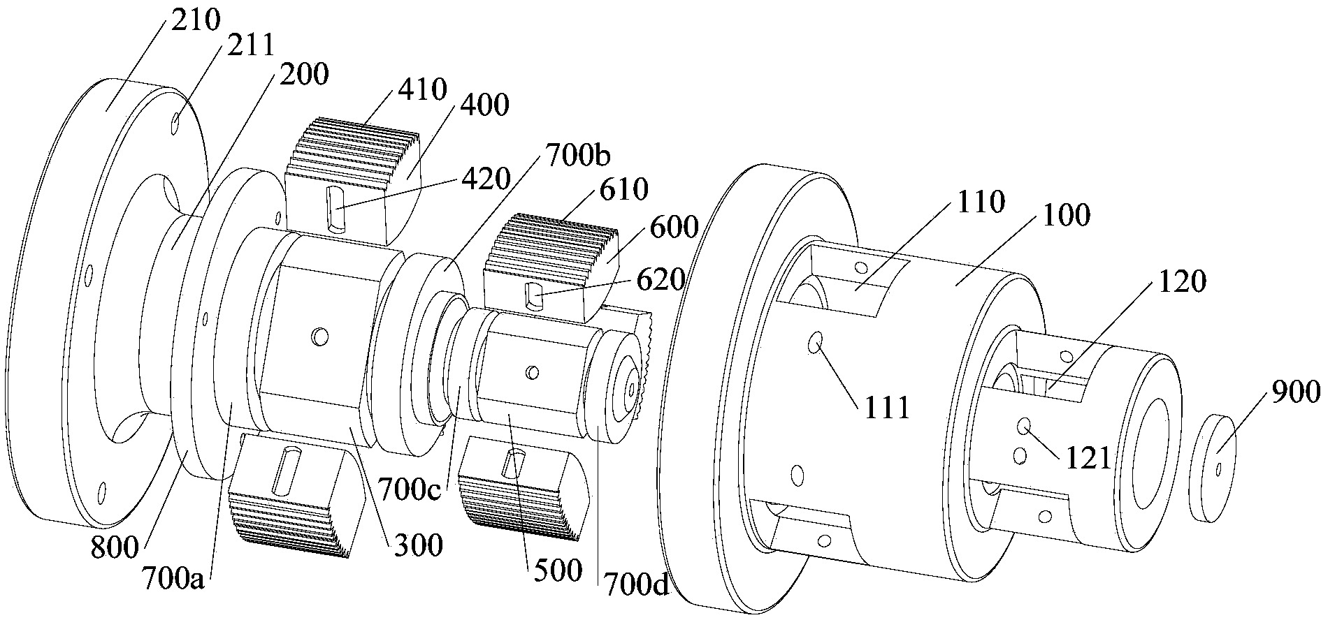
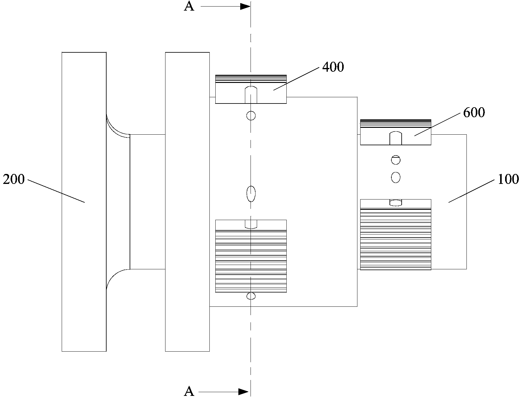
[0022] The invention provides a slitting machine unwinding and fixing device, see figure 1 and figure 2 , in one embodiment, the slitter unwinding fixture includes a cylindrical shell 100 and a central shaft 200 rotatably installed in the shell 100, considering the durability of the slitter unwinding fixture The problem is that both the shell 100 and the central shaft 200 are made of metal materials, such as carbon steel, stainless steel, etc., and one end of the central shaft 200 is provided with a mounting flange 210, through which the slitting machine can be unwound and fixed. Installed on the supporting slitting machine (for example, a high-speed slitting machine), in order to facilitate installation and disassembly, the mounting flange 210 is fastened on the corresponding parts of the slitting machine by bolts,...


PUM


Abstract

The invention discloses a slitter machine unrolling fixing device and a high-speed slitter machine. The slitter machine unrolling fixing device comprises a cylindrical outer shell and a center shaft which is installed in the outer shell in a rotatable mode. An installation flange is arranged at one end of the center shaft, and at least one ejecting mechanism is arranged in the axial direction of the center shaft. The ejecting mechanism comprises a cam and at least three ejecting blocks. The cross section of the cam is a regular polygon. The number of sides of the regular polygon is the same as that of the ejecting blocks. The cam is arranged on the center shaft, and the center line of the cam coincides with that of the center shaft. Radial holes are evenly formed in the periphery wall of the outer shell and correspond to all the ejecting blocks. The shape of the radial holes is matched with that of the ejecting blocks. Each ejecting block is embedded into the corresponding radial hole in a sliding mode. One end, located on the inner side of the outer shell, of each ejecting block is provided with an arc surface or a plane, the ejecting blocks are matched with the cam in a sliding mode, and one end, located on the outer side of the outer shell, of each ejecting block is provided with ejecting threads. In this way, only radial clamping force is exerted on a paper tube core, the two ends of the paper tube core will not deform after pressing, and therefore service life is prolonged.

Description

technical field [0001] The invention relates to the technical field of paper processing equipment, in particular to a slitting machine unwinding and fixing device and a high-speed slitting machine. Background technique [0002] Slitting machine is a kind of mechanical equipment that cuts wide-width paper, film and other raw materials into multiple narrow-width materials. Its main mechanism usually includes slitting part, unwinding part, winding part and guide roller part. In the prior art, the unwinding part is composed of a clamping drive device, an unwinding frame, and chucks arranged at both ends of the unwinding frame. The chuck is a solid structure with a taper. Distributed pre-tightening teeth, the clamping drive device can drive the chucks at both ends to make a linear motion towards and away from each other, so as to clamp and loosen the paper core sleeved on the two chucks. However, in actual production, it often occurs that the two ends of the paper tube core are ...

Claims


Application Information

Patent Timeline
Patent Type & Authority Applications(China)
IPC IPC(8): B65H16/06B65H75/30
Inventor 赵杰罗伟雄凌卫东蔡勇
Owner SHENZHEN KUNHONG PRINTING
Why Eureka
Try Eureka