F rail connector structure of medium-and-low-speed magnetic suspension system rail

A joint structure and maglev technology, applied in the joints, tracks, roads and other directions of rails, can solve problems such as large impact of vehicle vibration, and achieve the effects of easy maintenance, reduced investment and operation and maintenance costs, and simple structure

Active Publication Date: 2014-08-06
CHINA RAILWAY ERYUAN ENG GRP CO LTD
View PDF8 Cites 19 Cited by
  • Summary
  • Abstract
  • Description
  • Claims
  • Application Information

AI Technical Summary

Problems solved by technology

During the operation process, the vertical irregularity (height difference) of the F rail exceeded the standard at this structure, which caused the gap between the induction coil and the induction plate of the vehicle’s linear motor to be too small, and the collision between the inductio

Method used


Image

  • F rail connector structure of medium-and-low-speed magnetic suspension system rail
  • F rail connector structure of medium-and-low-speed magnetic suspension system rail
  • F rail connector structure of medium-and-low-speed magnetic suspension system rail

Examples


Embodiment Construction

[0023] The present invention will be further described below in conjunction with the accompanying drawings and embodiments.

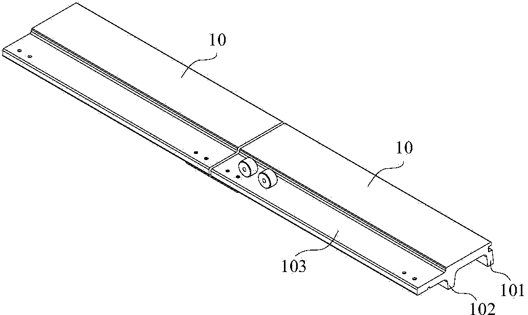
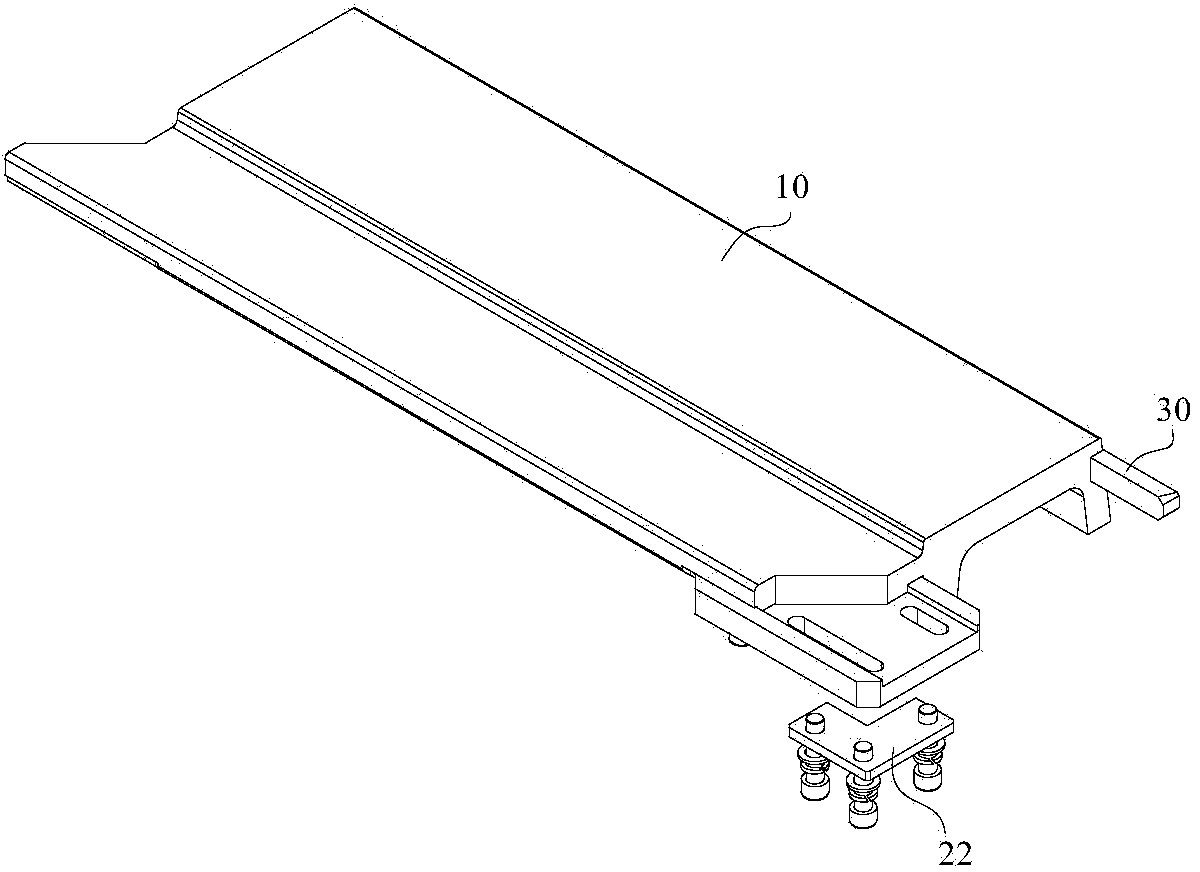
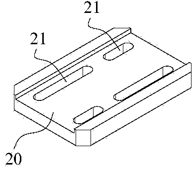
[0024] refer to figure 2 and Figure 5 , a medium-low speed maglev system track F rail joint structure of the present invention, two adjacent F rails 10 have outer legs 101, inner legs 102 and wing rails 103. refer to Figure 5 The inner bottom and the outer side wall of the two adjacent F rails 10 connected to the end wing rail 103 are provided with longitudinally extending inner guide limiting grooves 13 and outer guide limiting grooves 14 respectively, and the open end of the U-shaped connecting plate 20 Embed in the inner guide limiting groove 13 and the outer guide limiting groove 14. The inner guide limit groove 13, the outer guide limit groove 14 cooperate with the opening end of the U-shaped connecting plate 20, on the one hand, the contact area between the U-shaped connecting plate 20 and the wing rail 103 is widened, and on the other hand,...


PUM


Abstract

An F rail connector structure of a medium-and-low-speed magnetic suspension system rail aims to improve torsional stiffness and the altitude difference misalignment prevention ability of an F rail connector, and improve mounting precision of the rail. An inner guiding and limiting groove and an outer guiding and limiting groove which longitudinally extend are formed in the inner bottom and the outer side wall of a wing rail at the connecting end of each of two adjacent F rails respectively, the opening end of a U-shaped connecting plate is embedded into the inner guiding and limiting grooves and the outer guiding and limiting grooves, long slotted holes are formed in the U-shaped connecting plate in the longitudinal direction and the horizontal direction at intervals, and bolt connecting components which penetrate through the long slotted holes enable the U-shaped connecting plate and the two adjacent F rails to be detachably connected.

Description

technical field [0001] The invention relates to a medium-low speed maglev rail transit system, in particular to a track F rail joint structure of the medium-low speed maglev system. Background technique [0002] The medium and low-speed maglev rail transit adopts the suspension and guidance technology of the constant electromagnet suction type, and realizes the suspension and guidance of the vehicle through the electromagnetic attraction between the U-shaped electromagnet on the vehicle suspension frame and the F-shaped rail. At present, the medium and low speed maglev track structure that has been applied in China mainly adopts the steel sleeper type. The track is mainly composed of induction plates, F rails, expansion joints, connectors and fasteners, H-shaped steel sleepers, fastener systems, and ballast beds from top to bottom. (Rail-supporting platform) and other parts, and the rail row is used as a unit for overall paving. F rails, steel sleepers and induction plates ...

Claims


Application Information

Patent Timeline
IPC IPC(8): E01B11/26E01B25/30
Inventor 李艳蔡文锋颜华林红松张雷余浩伟
Owner CHINA RAILWAY ERYUAN ENG GRP CO LTD
Why Eureka
Try Eureka