Steel bar strapping machine

A binding machine and steel bar technology, which is applied in the processing of building materials, construction, building construction, etc., can solve problems such as low binding efficiency, reduced operating efficiency, and difficult torsion for workers, so as to ensure operating safety and improve operating efficiency. , the effect of reducing the amount of labor

Active Publication Date: 2014-08-06
SUZHOU BIAOTU SENIOR SEAT CO LTD
View PDF7 Cites 14 Cited by
  • Summary
  • Abstract
  • Description
  • Claims
  • Application Information

AI Technical Summary

Problems solved by technology

[0002] At present, iron wires and other wires are usually required to bind and position the steel frame on the construction site. Now this work is mainly done by manual operation. This manual operation has the following problems: low binding efficiency, inconvenient operation, non-standard binding, waste of binding use steel wire
During the twisting process, the torque increases continuously, so the iron wire is often broken due to excessive torque. Especially for manual steel bar binding machines, it is difficult for workers to control the appropriate torque. After the iron wire is twisted, it can only be tied again. It will lead to duplication of work, reduce work efficiency, and even cause safety accidents when the iron wire is in a half-twisted state.

Method used


Image

  • Steel bar strapping machine
  • Steel bar strapping machine
  • Steel bar strapping machine

Examples


Embodiment Construction

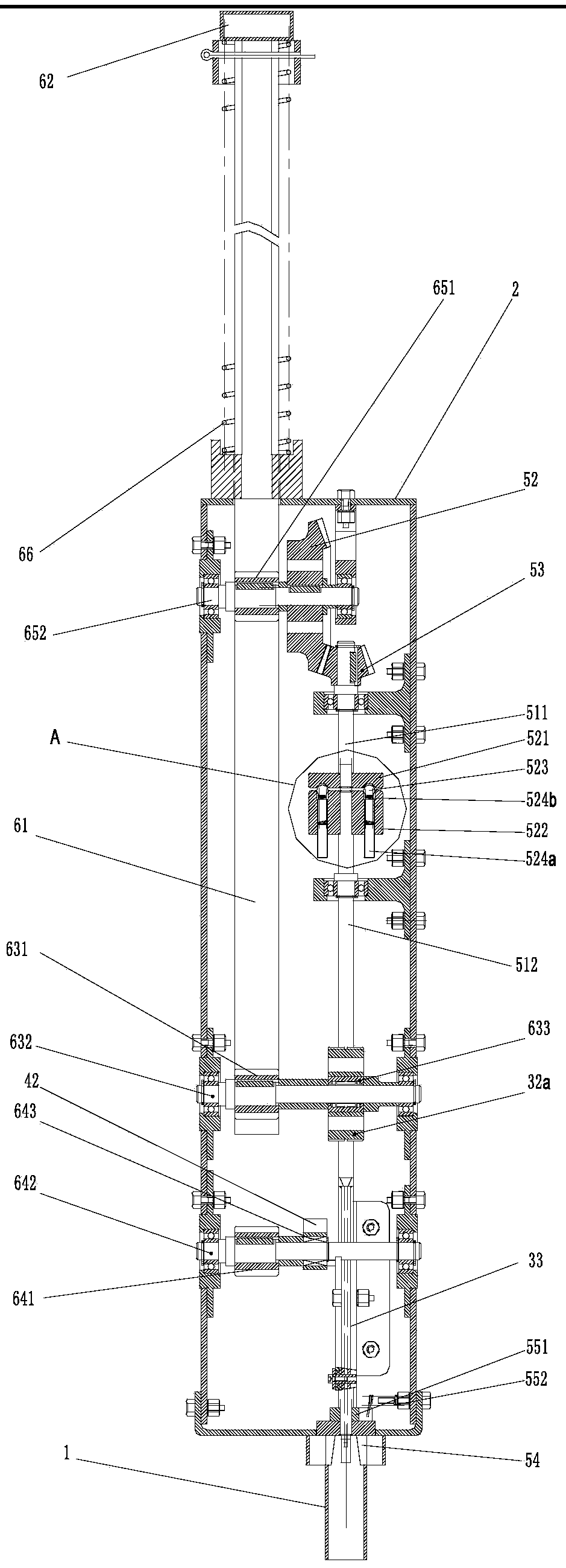
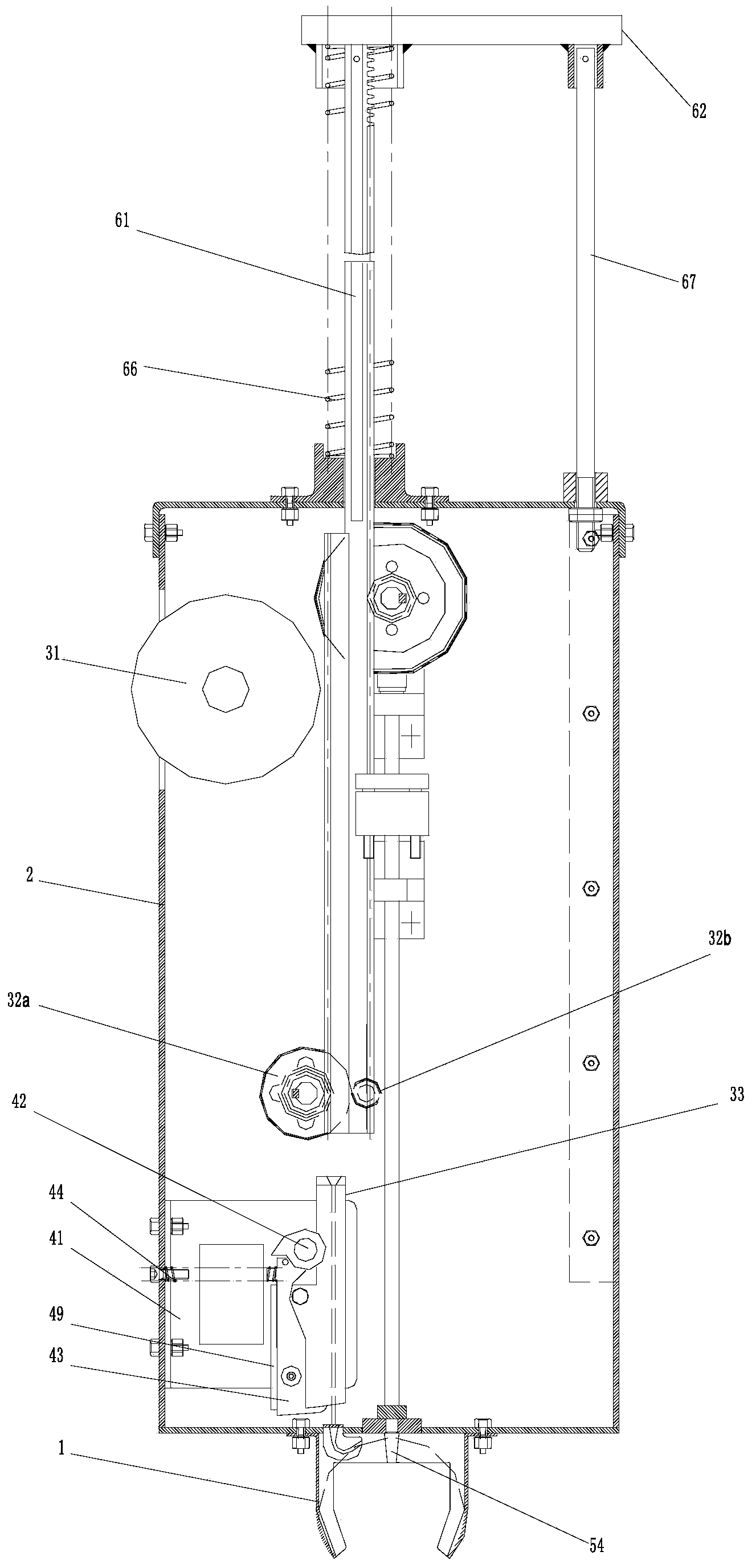
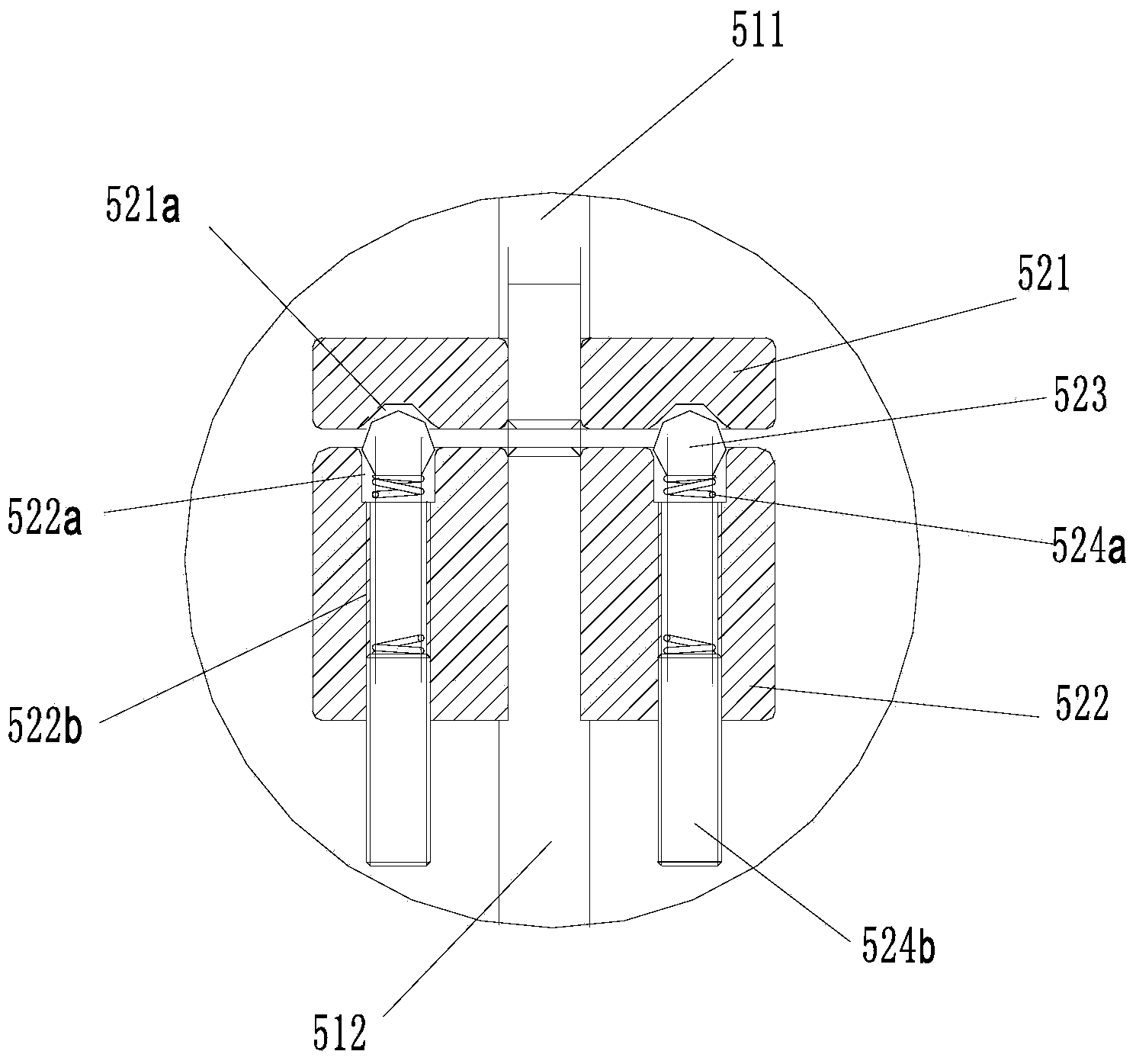
[0021] figure 1 It is the front view of the present invention, figure 2 It is the left view of the present invention, image 3 for figure 1 The enlarged picture at A in the middle is as shown in the figure: the steel bar binding machine of this embodiment includes a machine head 1, a housing 2, a transmission system and a wire feeding system, a wire cutting system and a twisting system fixed inside the housing 2. system, the twisting system includes a twisted shaft, the twisted shaft is a segmented structure and at least includes a driving shaft 511 and a driven shaft 512, and the twisting system also includes a shaft for connecting the driving shaft 511 and the driven shaft. The slipping device of the shaft 512; when the transmission torque between the driving shaft 511 and the driven shaft 512 exceeds the slipping torque of the slipping device, the transmission of the driving shaft 511 and the driven shaft 512 is disengaged; the twisted shaft design At least a two-stage ...


PUM


Abstract

The invention discloses a steel bar strapping machine which comprises a machine head, a casing, a transmission system, a wire feeding system fixed inside the casing, a wire cutting system and a stranding system. The stranding system comprises a stranding shaft, wherein the stranding shaft is of a segmented structure and comprises a driving shaft and a driven shaft at least. The stranding system further comprises a slipping device for being connected with the driving shaft and the driven shaft. When transfer torque between the driving shaft and the driven shaft exceeds slipping torque of the slipping device, the driving shaft breaks away from the driven shaft in a transmission mode. The stranding shaft of the steel bar strapping machine is designed to be of the structure provided with at least two segments, and the slipping device is added and enables the driving shaft and the driven shaft to be connected. When the transfer torque between the driving shaft and the driven shaft exceeds the preset slipping torque of the slipping device, the slipping device slips and accordingly enables the driven shaft to stop rotating and suspending stranding process, the torque control effect is achieved, iron wires are prevented from being twisted off, the labor amount of workers is reduced, the operation efficiency is improved, and the operation safety is ensured.

Description

technical field [0001] The invention relates to a binding machine, in particular to a steel bar binding machine. Background technique [0002] At present, iron wires and other wires are usually required to bind and position the steel frame on the construction site. Now this work is mainly done by manual operation. This manual operation has the following problems: low binding efficiency, inconvenient operation, non-standard binding, waste of binding use steel wire. Therefore, a steel wire binding machine has appeared on the market, which includes a machine head, a housing, a transmission system, and a wire feeding system, a wire cutting system, and a twisting system fixed inside the housing; the machine head is generally in the shape of a "C" A groove for positioning the steel frame is formed, and the iron wire passes through the deformation mechanism in the machine head (that is, the arc-shaped guide wire through hole) to bundle the steel frame in an arc-shaped surrounding ...

Claims


Application Information

Patent Timeline
Patent Type & Authority Applications(China)
IPC IPC(8): E04G21/12
Inventor 董小闵李高山毛飞
Owner SUZHOU BIAOTU SENIOR SEAT CO LTD
Why Eureka
Try Eureka