
A device and method for sand removal in marine natural gas hydrate production wells

A technology for natural gas and hydrate, which is applied in the fields of fluid production, earth-moving drilling, wellbore/well components, etc. It can solve the problems of blockage, structural limitation, and arrangement at the well outlet on the surface, so as to improve sand removal efficiency and reduce equipment wear effect

Active Publication Date: 2017-01-04
DALIAN UNIV OF TECH
View PDF6 Cites 1 Cited by
  • Summary
  • Abstract
  • Description
  • Claims
  • Application Information

AI Technical Summary

Problems solved by technology

However, in order not to affect the production efficiency, the filter pore size of the sand filter tube should not be too small, so it is still impossible to prevent the sand with a smaller particle size from entering the wellbore, and the impact of the fine particle size silt on the wear of the wellbore and the pump cannot be ignored, so It is necessary to further isolate the movement of fine silt to the wellbore
Most of the traditional mechanical desanding devices adopt the filtering method (such as ZL99254473.4), however, the filtering effect is limited by the mesh size of the filter mesh, if it is too large, it will not be able to filter fine sand; if it is too small, it will easily cause blockage
Unable to meet sand removal requirements
In addition, there are methods of sand removal using cyclone (ZL00215037.9, ZL200820122916.4, CN203214037), but due to structural limitations, most of these devices can only be arranged at the exit of wells on the ground, and do not fundamentally solve the problem of sand removal before wells. question

Method used


Image

  • A device and method for sand removal in marine natural gas hydrate production wells
  • A device and method for sand removal in marine natural gas hydrate production wells
  • A device and method for sand removal in marine natural gas hydrate production wells

Examples


Embodiment Construction

[0021] specific implementation plan

[0022] Combine below figure 1 , figure 2 The present invention is described in detail with examples.

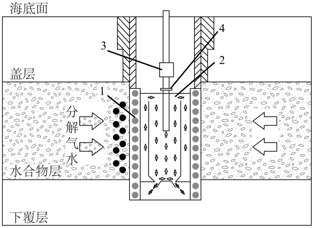
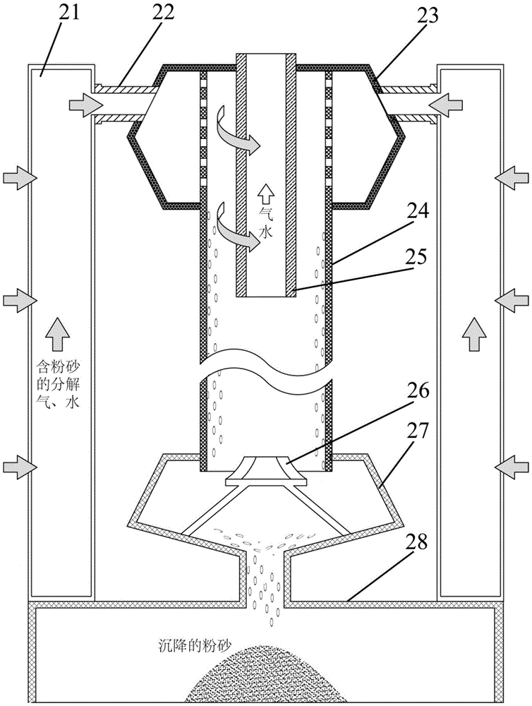
[0023] 1. After the drilling is completed, the gravel packing group 1 is first lowered to the bottom of the wellbore, and then the centrifugal desander 2 and the submersible pump 3 are connected with the connecting flange 4 and lowered to the bottom of the wellbore as a whole, such as figure 1 As shown, at this time, the outer wall of the diversion chamber 21 of the centrifugal desander is attached to the inner wall of the gravel packing group 1;

[0024] 2. After the mining starts, the gas, water and mobile sand produced by the decomposition of the natural gas hydrate layer flow to the wellbore. The larger sediment particles are blocked by the gravel packing group 1, and the smaller particles of silt enter the centrifugal removal along with the decomposed gas and water. sander 2;

[0025] 3. The decomposed gas and water containing s...


PUM


Abstract

The invention provides a device and method for desanding of a submarine natural gas hydrate exploitation well. The device comprises a gravel filling set, a centrifugal desander, a submerged pump and a connecting flange. The gravel filling set is arranged at the bottom of the exploitation well, the centrifugal desander and the submerged pump are connected through the connecting flange and wholly descend to the bottom of the exploitation well, and the outer wall of a flow guide chamber is attached to the inner wall of the gravel filling set. By the adoption of the device, in the centrifugal desanding process, gas-water sand is firstly decomposed and flows to a shaft, large settled layer sand is blocked by the gravel filling set, and gas and water containing fine sand enters the shaft; gas and water containing the fine sand enter an upper collection box through the flow guide chamber and an inflow port, and cyclones are generated; under the effect of centrifugal force, the fine sand is gathered on the inner wall of a settling chamber and descends into a sand collection box. By the adoption of a secondary desanding method, desanding efficiency is improved, and permeability of a hydrate settled layer cannot be remarkably affected; by the adoption of a cyclone centrifugal mode, the fine sand and decomposed gas and water can be effectively separated, the fine sand is prevented from entering the submerged pump, and equipment wear is reduced.

Description

technical field [0001] The invention relates to a device and method for sand removal in marine natural gas hydrate production wells, and belongs to the technical field of exploitation of marine oil and gas reservoirs (including new oil and gas reservoir resources such as natural gas hydrates). Background technique [0002] Sand production in oil and gas wells is due to the destruction of the rock formation structure near the bottom of the production well, which causes sand particles to move to the wellbore with the fluid. In severe cases, it will cause a decrease in permeability, blockage of tubing, and a decline in production. The natural gas hydrate production process is accompanied by the decomposition of the hydrate layer, and the original cementation state changes. A large number of sediment particles that can flow with the decomposed gas and water are produced near the production well, and the problem of sand production is more serious than that of conventional oil and ...

Claims


Application Information

Patent Timeline
Patent Type & Authority Patents(China)
IPC IPC(8): E21B43/34
Inventor 刘瑜宋永臣赵佳飞
Owner DALIAN UNIV OF TECH
Learn More