Turbine shaft engine

A turboshaft engine and turbine technology, applied in the direction of machines/engines, gas turbine devices, mechanical equipment, etc., can solve problems such as difficulties, unfavorable power-to-weight ratio, increased weight and volume, etc.

Inactive Publication Date: 2014-08-06
李吉光
View PDF0 Cites 3 Cited by
  • Summary
  • Abstract
  • Description
  • Claims
  • Application Information

AI Technical Summary

Problems solved by technology

[0002] In a turboshaft engine, increasing the supercharging ratio of the compressor can increase the power and reduce the fuel consumption rate. To increase the supercharging ratio, at present, it is mainly to increase the number of stages of the compressor and the turbine or to increase the gas temperature before the turbine, but the former Increasi...

Method used


Image

  • Turbine shaft engine
  • Turbine shaft engine

Examples


Embodiment Construction

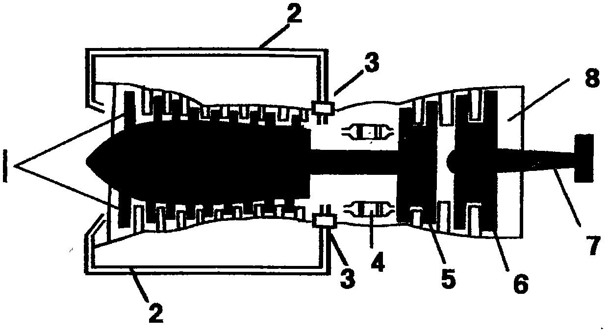
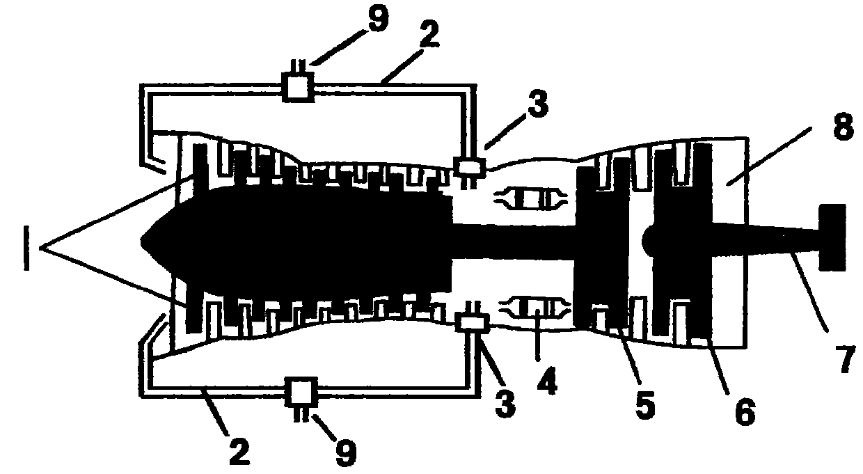
[0011] Refer to attached figure 1 and 2 , the turboshaft engine of the present invention includes an axial flow compressor 1, a bypass pipe 2, an internal exhaust valve 3, an evaporative combustion chamber 4, a turbine 5, a free turbine 6, a drive shaft 7, a tail nozzle 8, etc. , wherein the intake port of the bypass pipe 2 is between the rear of the axial flow compressor 1 and the front of the evaporative combustion chamber 4, and is connected to the engine through the internal exhaust valve 3 located between them, and its air outlet is at or toward the engine intake Air port; there can be no external exhaust valve 9 in the pipe outside the engine between the air inlet and outlet of bypass pipe 2, such as figure 1 shown; there may also be an external exhaust valve 9, such as figure 2 As shown, its function is to adjust the pressure of the compressed air in the bypass pipe 2.

[0012] When the turboshaft engine is the present invention figure 1 , 2 In the case of the tur...


PUM


Abstract

A turbine shaft engine comprises axial-flow compressors, evaporative combustors, a turbine, a free turbine, a drive shaft, an exhaust nozzle and the like, and is characterized by further comprising by-pass pipes and internal exhaust valves, and external exhaust valves are mounted or are not mounted in pipes outside the engine and between air inlets and air outlets of the by-pass pipes; and when the engine is started for operation, the internal exhaust valves are opened, the supercharge ratios of the axial-flow compressors are increased and kept unchanged by means of the by-pass pipes and through opening and closing of the internal exhaust valves or the internal exhaust valves and the external exhaust valves, the increased supercharge ratios are not larger than the mechanical strength limit which can be borne by the axial-flow compressors, the turbine and the free turbine, the turbine inlet temperature is kept unchanged, that is, the supercharge ratios and a power weight ratio are increased, the oil consumption rate is reduced, however, the number of stages of the axial-flow compressors and the turbines is not increased, and the turbine inlet temperature is not improved.

Description

technical field [0001] The invention relates to a turboshaft engine, in particular to a turboshaft engine capable of increasing the supercharging ratio, and belongs to the technical field of turboshafts, especially military turboshaft engines. Background technique [0002] In a turboshaft engine, increasing the supercharging ratio of the compressor can increase the power and reduce the fuel consumption rate. To increase the supercharging ratio, at present, it is mainly to increase the number of stages of the compressor and the turbine or to increase the gas temperature before the turbine, but the former Increasing the weight and volume is not conducive to improving the power-to-weight ratio. The latter must use high-temperature-resistant, high-performance turbine blade materials, coating materials, and advanced cooling technologies. It is very difficult to improve, and the current turboshaft engine The supercharging ratio is fixed and cannot be changed or improved. Content...

Claims


Application Information

Patent Timeline
IPC IPC(8): F02C3/34F02C9/18
Inventor 李吉光
Owner 李吉光
Why Eureka
Try Eureka