Negative pressure supply device for engine

A technology for supplying devices and engines, which is applied to engine components, combustion engines, machines/engines, etc., can solve the problems of complex piping structure and large number of components, and achieve the effects of easy layout, improved performance, and improved rigidity

Inactive Publication Date: 2018-01-12
SUZUKI MOTOR CORP
View PDF9 Cites 0 Cited by
  • Summary
  • Abstract
  • Description
  • Claims
  • Application Information

AI Technical Summary

Problems solved by technology

Such a vacuum pump is often assembled on the cylinder head, but in the negative pressure supply device of the engine described in Japanese Patent Application Laid-Open No. 2003-74411, although the negative pressure working equipment is arranged near the cylinder head, it still consists of pipes made of metal. The negative pressure forming passage member connects these negative pressure working equipment and the vacuum pump, so the piping structure is complicated, and the number of parts such as fixing pieces for fixing metal pipes is large.

Method used


Image

  • Negative pressure supply device for engine
  • Negative pressure supply device for engine
  • Negative pressure supply device for engine

Examples


Embodiment Construction

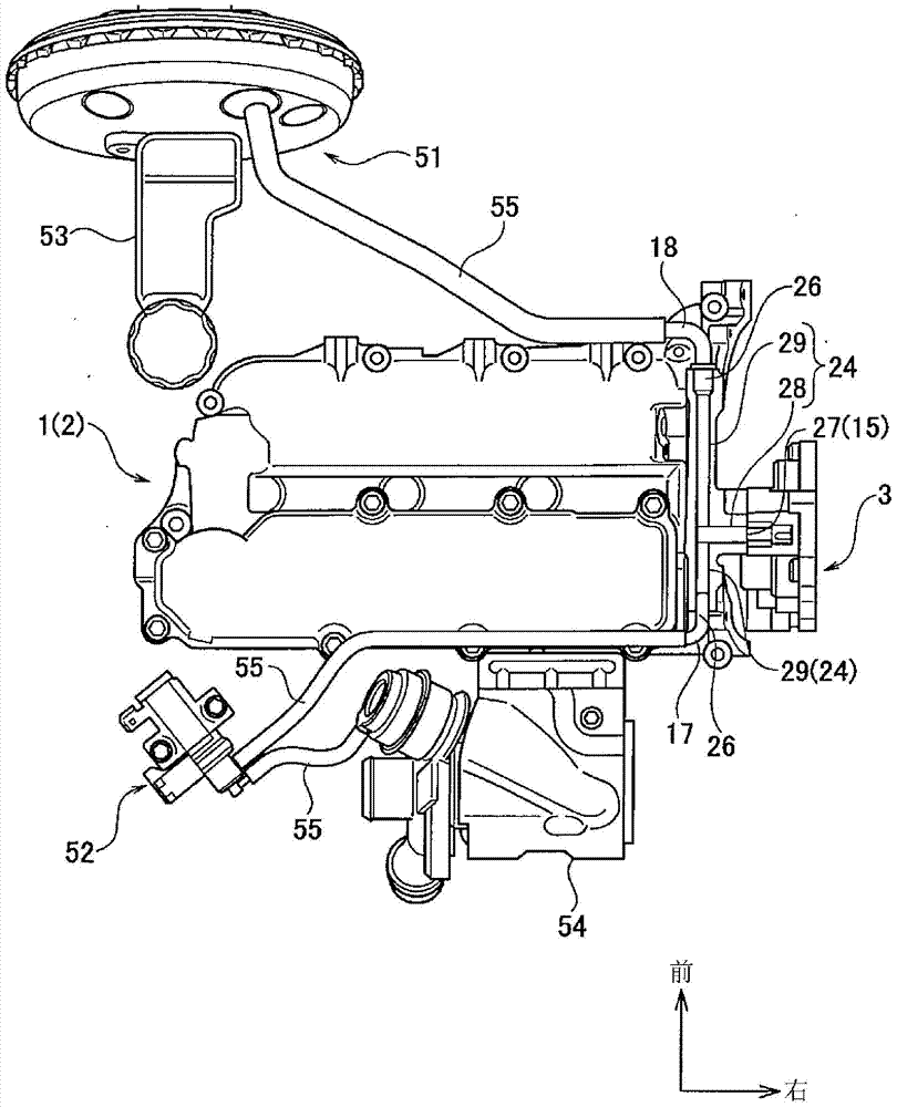
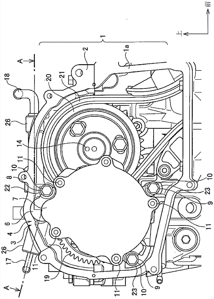
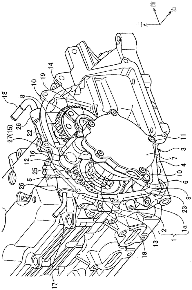
[0015] An embodiment of a negative pressure supply device for an engine according to the present invention will be described below with reference to the drawings. figure 1 is a plan view of the cylinder head of the present embodiment, figure 2 is showing figure 1 Front view of the assembly structure of the vacuum pump in the cylinder head, image 3 yes figure 1 Perspective view of the negative pressure supply device in the cylinder head. In the engine of the present embodiment, a cylinder head 1 is mounted above a cylinder block (not shown). The cylinder head 1 of the present embodiment includes: a cylinder head lower portion 1a mounted above the cylinder block; and a cam box 2 mounted above the cylinder head lower portion 1a. In addition, the engine main body is mounted on the vehicle in various directions, but usually the cylinder head 1 is mounted above the cylinder block, so this direction is defined as the upper side of the engine, and the opposite direction is defin...


PUM


Abstract

Disclosed is a negative pressure supply device for an engine capable of simplifying the piping structure and improving the rigidity of the cylinder head. Assemble the vacuum pump (3) on the cylinder head (1), connect the suction port (15) connected with the pump suction port (27) of the vacuum pump (3) and the negative pressure outlet (17, The negative pressure passage (24) in the cylinder head of 18) is formed in the wall of the cylinder head (1), and the piping used to connect the negative pressure outlets (17, 18) and connect with the negative pressure passage (24) in the cylinder head The coupling portion (26) is arranged outside the wall portion of the cylinder head (1). In the case where two connecting holes (29) whose axes are perpendicular to one communicating passage (28) are formed opposite to each other, the ribs constituting the outer wall of the communicating passage (28) and the connecting hole (29) and the cylinder head (1 ) is continuously formed on the outer side of the wall portion, and the rigidity of the cylinder head (1) is improved.

Description

technical field [0001] The present invention relates to a negative pressure supply device for supplying negative pressure to a negative pressure working device used in a vehicle, and is particularly suitable for a negative pressure supply for an engine that supplies negative pressure to a negative pressure working device through a vacuum pump mounted on a cylinder head of an engine. device. Background technique [0002] Vacuum pumps have the function of generating negative pressure using rotational driving force, and the negative pressure is used in engine negative pressure operating equipment such as vacuum boosters for brakes and VSV (Vacuum Switching Valve: Vacuum Switching Valve) for turbocharger control. As a negative pressure supply device for an engine using such a vacuum pump, there is, for example, the negative pressure supply device described in Japanese Unexamined Patent Application Publication No. 2003-74411. In the negative pressure supply device of the engine,...

Claims


Application Information

Patent Timeline
Patent Type & Authority Patents(China)
IPC IPC(8): F02F1/42
CPCF02B67/04F02B37/186
Inventor 金子裕之
Owner SUZUKI MOTOR CORP
Why Eureka
Try Eureka