Dust remover by-pass valve

A dust collector and bypass valve technology, which is applied to lift valves, valve devices, engine components, etc., can solve the problems of easy dust accumulation of bypass valves and low installation accuracy requirements, achieve low production and installation accuracy requirements, and ensure long-term reliability. Use and ensure the effect of zero leakage of the bypass

Inactive Publication Date: 2014-08-06
FUJIAN LONGKING
View PDF13 Cites 2 Cited by
  • Summary
  • Abstract
  • Description
  • Claims
  • Application Information

AI Technical Summary

Problems solved by technology

[0006] The purpose of the present invention is to solve the above-mentioned problems existing in the existing bypass valve, provide a bypass valve that can realize long-term zero leakage, low installation accuracy requirements, solve the problem that the bypass valve with a sealed coil structure is easy to accumulate dust, and the annular cone surface is well sealed and can be used. Guaranteed long-term reliable use, no need to provide additional sealing gas, a new type of dust collector bypass valve for energy saving

Method used


Image

  • Dust remover by-pass valve
  • Dust remover by-pass valve
  • Dust remover by-pass valve

Examples


Embodiment Construction

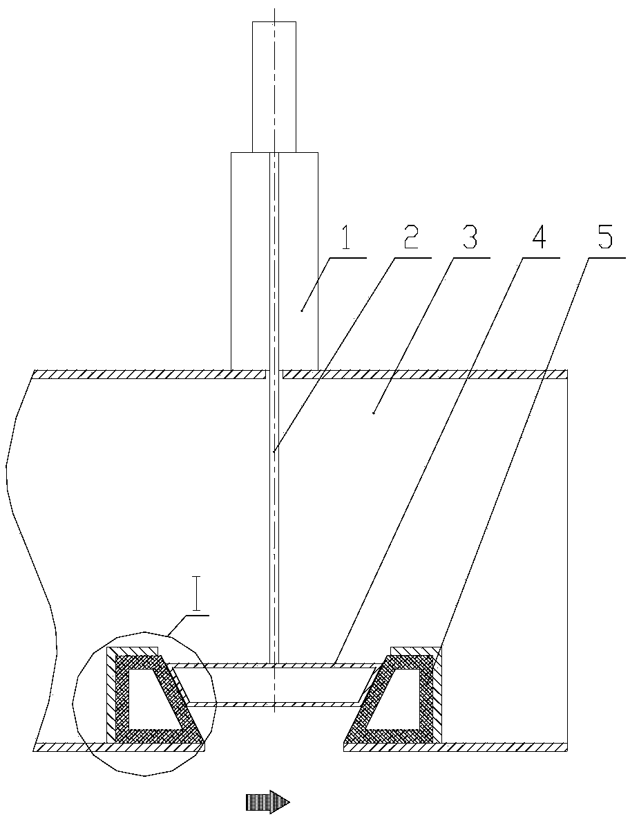
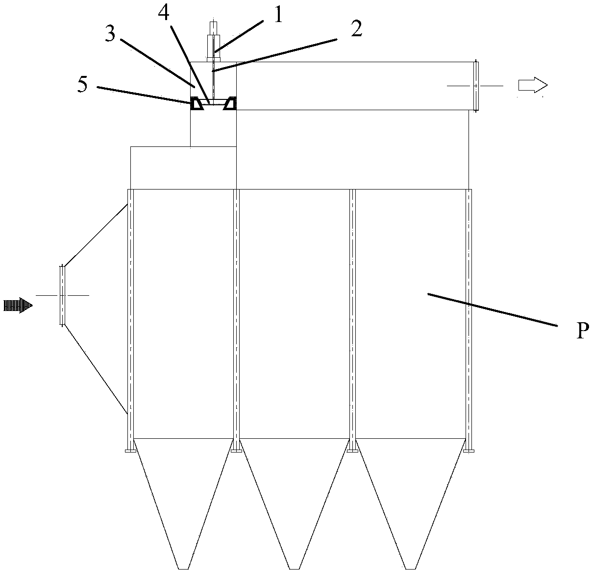
[0019] Such as Figure 1~5 As shown, the embodiment of the present invention is provided with a power unit 1 , a lifting rod 2 , a valve plate 4 and a valve seat 5 . The upper part of the lifting rod 2 is connected with the power unit 1, and the bottom end of the lifting rod 2 is fixedly connected to the top of the valve plate 4. The valve plate 4 and the valve seat 5 adopt an annular cone surface structure, and the outer annular cone surface of the valve plate 4 is in contact with the valve plate. The inner annular cone surface of the seat 5 is sealed and fitted; the valve seat 5 is arranged on the inner side of the inlet of the air duct 3 of the dust collector. exist Figure 1~5 In the figure, the arrow indicates the flue gas; the mark P is the dust collector; the mark A is the sealing surface.

[0020] The taper of the inner annular tapered surface of the valve seat 5 is 10-60°.

[0021] The power device 1 can be a cylinder, and the power device 1 is used to push the val...


PUM


Abstract

The invention provides a dust remover by-pass valve and relates to a dust remover. The dust remover by-pass valve is provided with a power device, a lifting rod, a valve plate and a valve seat. The upper portion of the lifting rod is connected with the power device. The bottom end of the lifting rod is fixedly connected to the top of the valve plate, the valve plate and the valve seat are of annular conical surface structures, and the outer side annular conical surface of the valve plate is in sealing matched connection with the inner side annular conical surface of the valve seat. The valve seat is arranged on the inner side of the inlet position of a dust remover air duct and provided with an elastic sealing material layer. Sealing is achieved through the annular conical surfaces of the valve seat and the valve plate, a sealing coil structure mode of an existing by-pass valve is completely changed, shortcomings of an original sealing mode are overcome, and by-pass zero leakage is ensured. In addition, the manufacture and installation accuracy requirements are low, and the problem that dust easily accumulates on a line-sealed by-pass valve can be solved. Due to the fact that the dust remover by-pass valve is sealed by adopting the annular conical surfaces, the leakage problem caused by thermal expansion and cold contraction in the running process in a line-sealing mode is solved, long-period reliable usage can be ensured, additional sealing gas is not needed, and the dust remover by-pass valve has the advantage of saving energy.

Description

technical field [0001] The invention relates to a dust collector, in particular to a dust collector bypass valve. Background technique [0002] With the improvement of people's requirements for air quality, the country's requirements for dust emissions are becoming more and more stringent. Coal-fired boilers, industrial boilers and other kilns with large dust emissions must install high-efficiency dust collectors, and bag filter and electric bag composite dust collector are currently the most effective dust removal equipment for controlling dust emissions. Therefore, the application of bag filter and electric bag filter is booming. [0003] National standards for air pollutant emissions from thermal power plants have been promulgated, requiring dust emissions to be less than 30mg / Nm 3 , key areas require less than 20mg / Nm 3 . The draft of air pollutant emission standards for the cement industry also requires dust to be less than 30mg / Nm 3 . The introduction of these hi...

Claims


Application Information

Patent Timeline
Patent Type & Authority Applications(China)
IPC IPC(8): F16K1/00F16K1/42
CPCF16K1/385F16K1/42F16K1/465
Inventor 朱召平邱毅锋
Owner FUJIAN LONGKING
Why Eureka
Try Eureka