Outdoor lighting lamp

A technology for outdoor lighting and lamps, used in outdoor lighting, lighting devices, fixed lighting devices, etc., can solve the problems of short service life of LED light-emitting components and control components, accelerated metal heat dissipation plates, low heat exchange efficiency, etc. Heat dissipation, reduce sunlight exposure, good heat dissipation effect

Active Publication Date: 2014-08-06
NINGBO TENGLONG OUTDOOR IMPLEMENT
View PDF9 Cites 1 Cited by
  • Summary
  • Abstract
  • Description
  • Claims
  • Application Information

AI Technical Summary

Problems solved by technology

[0002] Outdoor lighting fixtures such as LED street lights generally have high power. During use, the LED light-emitting components and control components in the lamps will generate a lot of heat. Heat dissipation with the control components to ensure the normal operation of the lamps. At present, there are two main heat dissipation methods for lamps. The first heat dissipation method is to mount the LED light-emitting components on a metal heat sink with good thermal conductivity, and place the control components on the Fix it on the metal heat sink, and then open the heat dissipation hole on the lamp shell. During the use of the lamp, the heat generated by the LED light-emitting element and the control element is transferred to the metal heat sink, and the heat exchange between the metal heat sink and the air makes the LED The heat generated by the light-emitting element and the control element is continuously taken away to achieve the purpose of heat dissipation, but this heat dissipation method requires the metal heat dissipation plate to have better thermal conductivity and requ

Method used


Image

  • Outdoor lighting lamp
  • Outdoor lighting lamp
  • Outdoor lighting lamp

Examples


Embodiment Construction

[0020] The present invention will be further described in detail below in conjunction with the drawings and specific embodiments.

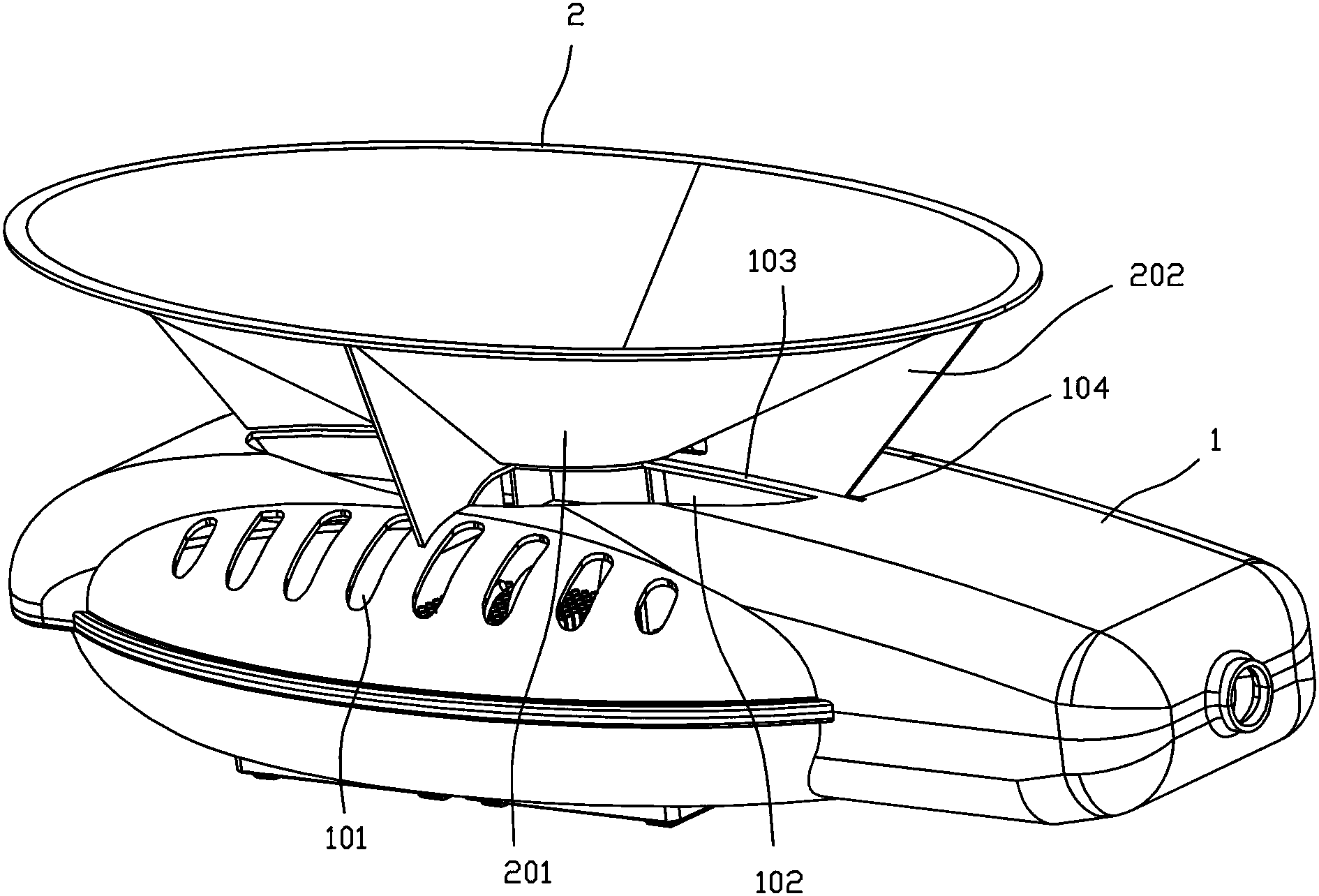
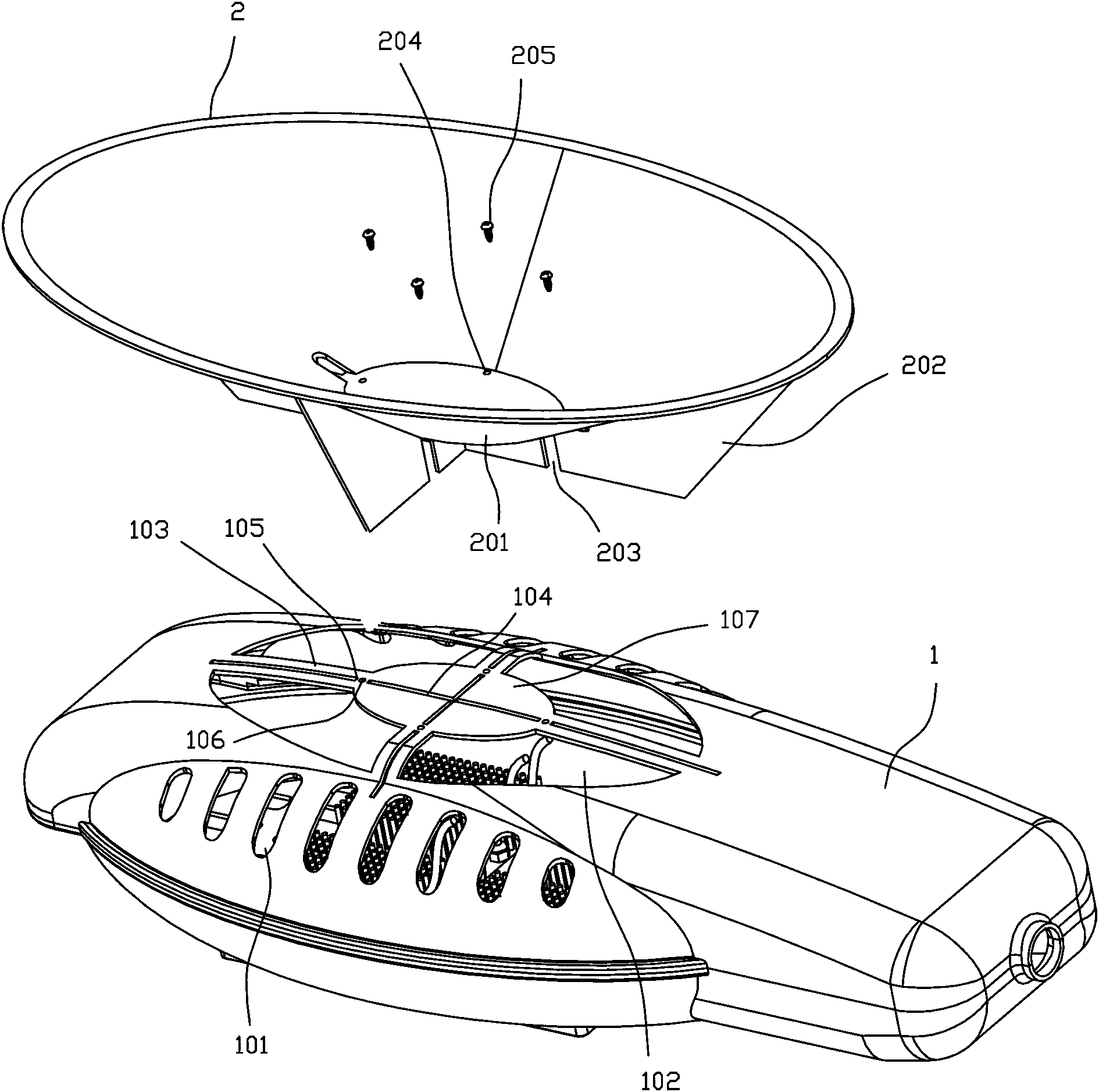
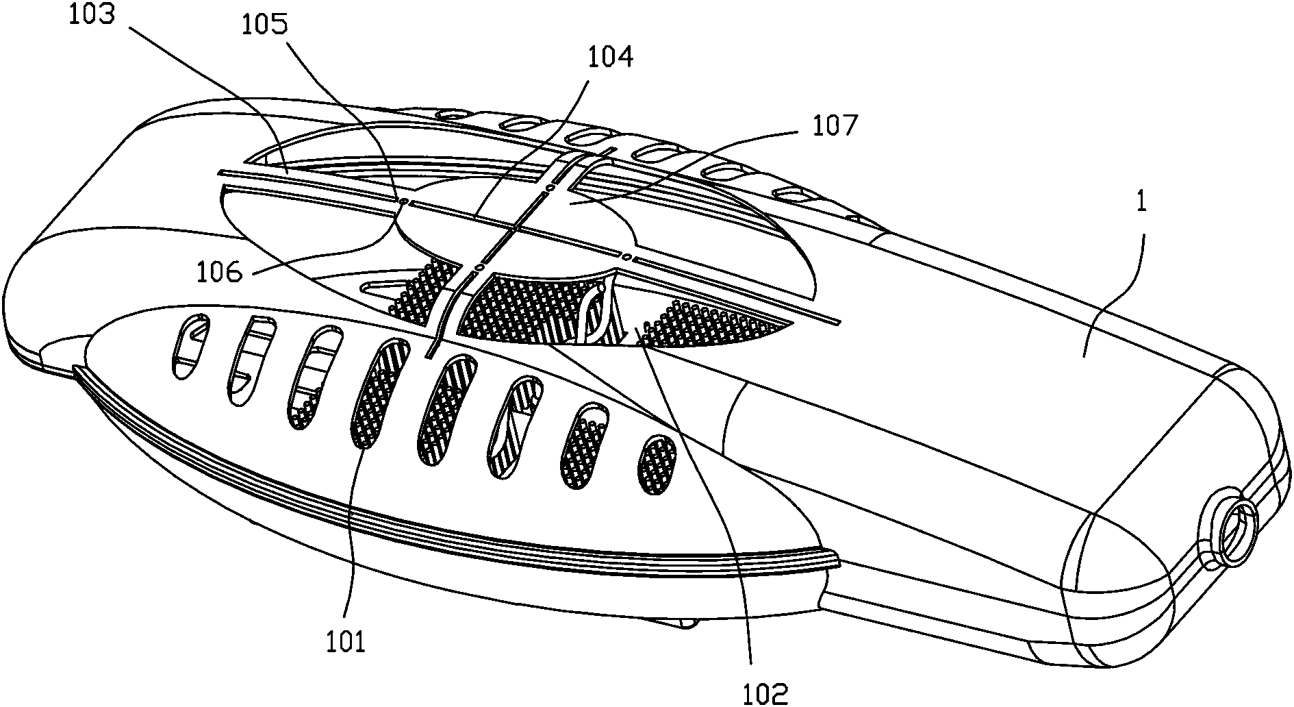
[0021] by figure 1 , figure 2 As shown, the outdoor lamp of the present invention includes a lamp housing 1 and a wind guide member 2.

[0022] The lamp housing 1 is provided with a heat dissipation plate, and heating elements such as LED light-emitting elements and control elements in the lamp housing are installed on the heat dissipation plate, and the heat generated by the heating elements is transferred to the heat dissipation plate for heat dissipation.

[0023] The wind guide member 2 is arranged above the lamp housing 1. The wind guide member 2 has an outer side wall 201 that extends obliquely and upwards from the upper part of the lamp housing 1 to the upper side of the lamp housing 1. The outer side of the wind guide member At least two partitions 202 are provided on the wall 201, and the partitions 202 extend obliquely upwards from the upper s...


PUM


Abstract

The invention discloses an outdoor lighting lamp. The outdoor lighting lamp comprises a lamp shell and a wind guide part. A heat sink is arranged inside the lamp shell. The wind guide part is arranged on the upper portion of the lamp shell. The wind guide part is provided with an outer side wall which extends upwards in an inclined mode from the upper portion of the lamp shell towards the upper portion of one side of the lamp shell. At least two partition plates are arranged on the outer side wall of the wind guide part and extend upwards in an inclined mode along the outer side wall of the wind guide part from the upper surface of the lamp shell. A wind inlet hole is formed in the upper portion or one side of the lamp shell. The outer side wall of the wind guide part is located above the wind inlet hole. When natural wind blows the outer side wall of the wind guide part, the outer side wall of the wind guide part and the partition plates change the direction of the natural wind and make the natural wind blow the heat sink through the wind inlet hole. According to the outdoor lighting lamp, the natural wind can be guided into the lamp shell, so that the heat dissipation effect is better, and the lamp shell can be less irradiated by sunlight; besides, the manufacturing cost is quite low, and manufacturing is convenient.

Description

technical field [0001] The invention relates to an outdoor lighting fixture with good heat dissipation effect and long service life. Background technique [0002] Outdoor lighting fixtures such as LED street lights generally have high power. During use, the LED light-emitting elements and control elements in the light will generate a lot of heat. It is necessary to dissipate heat from the LED light-emitting elements and control elements to ensure the normal operation of the light. There are two main heat dissipation methods. The first heat dissipation method is to mount the LED light-emitting element on a metal heat dissipation plate with good thermal conductivity, and fix the control element on the metal heat dissipation plate, and then set a heat dissipation device on the lamp housing. During the use of the lamp, the heat generated by the LED light-emitting elements and control elements is transferred to the metal heat sink, and the heat exchange between the metal heat si...

Claims


Application Information

Patent Timeline
IPC IPC(8): F21S8/00F21V29/00F21W131/10
Inventor 刘坚
Owner NINGBO TENGLONG OUTDOOR IMPLEMENT
Why Eureka
Try Eureka