Dehumidifier

A technology of dehumidifier and humid air, which is applied in household heating, space heating and ventilation details, heating methods, etc. It can solve problems such as unsatisfactory dehumidification effect, energy waste, and poor cooling effect, and achieve low-temperature defrosting Problems, simple and reasonable structural design, and the effect of improving the dehumidification effect

Inactive Publication Date: 2014-08-06
NANJING TIEDAN ELECTRICAL APPLIANCE TECH
View PDF8 Cites 9 Cited by
  • Summary
  • Abstract
  • Description
  • Claims
  • Application Information

AI Technical Summary

Problems solved by technology

[0003] For the above traditional compression dehumidifiers, part of the cooling capacity of the evaporator is taken away by condensed water, and the remaining sensible cooling air does not have a good cooling effect on the condenser, which will increase the operating load of the compressor and make the dehumidifier The energy consumption is increased, and the dehumidification capacity is also reduced. Especially when the evaporator is frosted when operating at low temperature, the dehumidification must be stopped for defrosting, and the dehumidification effect is not ideal.
The dry hot gas discharged from the condenser is emitted into the air, which not only increases the room temperature, but also wastes the energy discharged.
[0004] Therefore, there is a great need for an improved dehumidifier to solve the current situation of high energy consumption, energy waste, and unsatisfactory dehumidification effect of existing dehumidifiers, so as to facilitate the use of dehumidifiers at home without increasing the room temperature and improve its dehumidification efficiency.

Method used


Image

  • Dehumidifier
  • Dehumidifier
  • Dehumidifier

Examples


Embodiment Construction

[0024] The present invention will be further described below through embodiment and accompanying drawing. It should be understood that these embodiments are only used to illustrate the present invention and are not intended to limit the scope of the present invention. After reading the present invention, those skilled in the art all fall into the appended claims of the present application to the amendments of various equivalent forms of the present invention limited range.

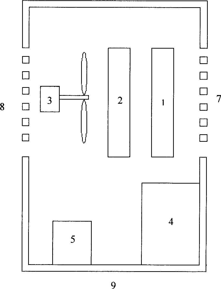
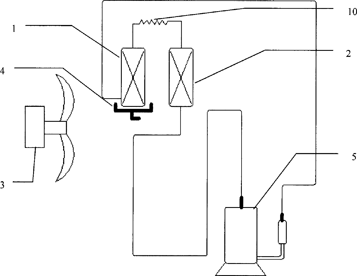
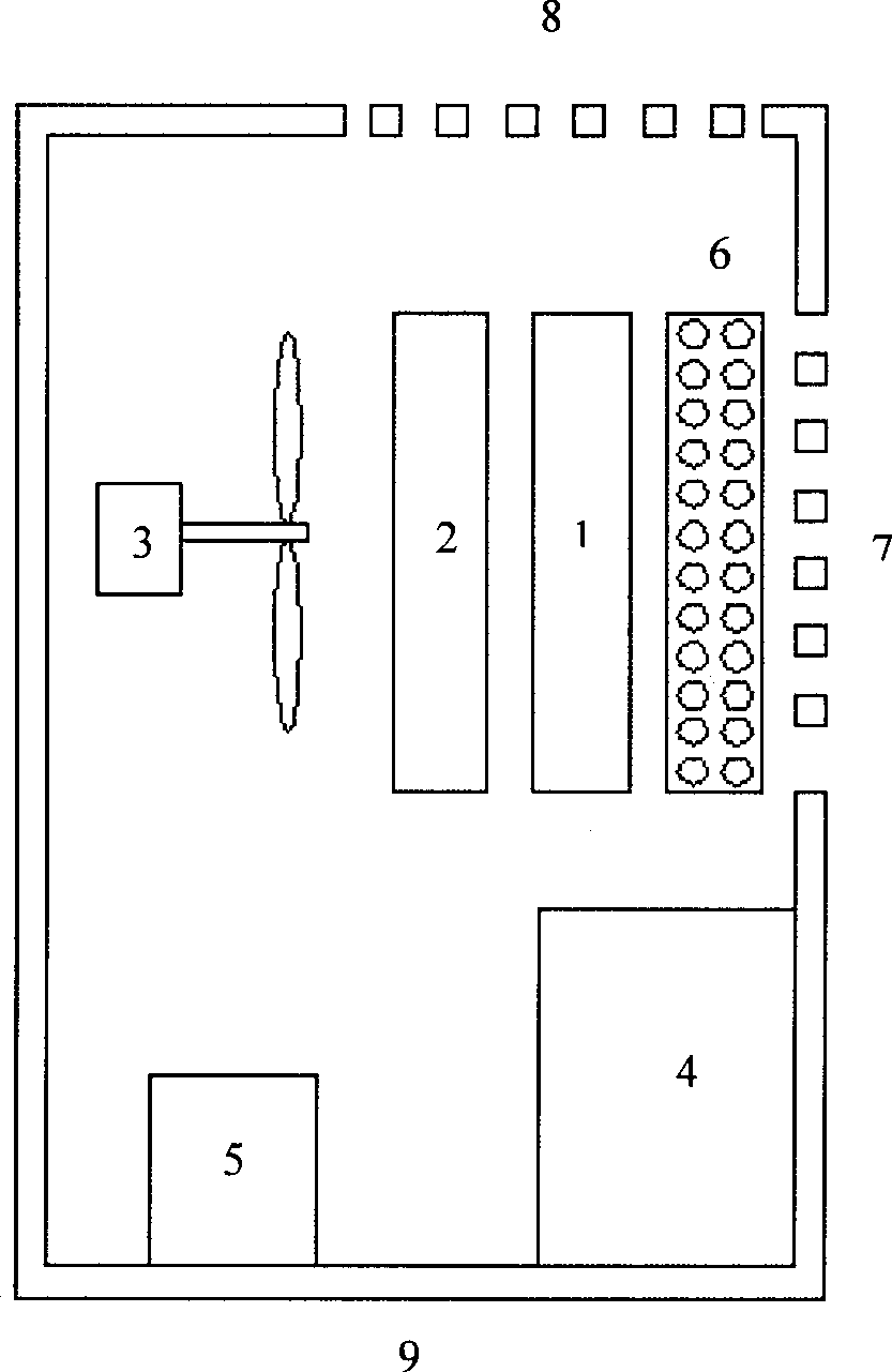
[0025] For a schematic sectional view and a schematic structural schematic view of a preferred embodiment of the dehumidifier of the present invention, please refer to image 3 and Figure 4 . In this dehumidifier, a fan 3, a water tank 4, an energy recovery device 6 and a compressor 4, a condenser 2, an evaporator 1, and a capillary tube 10 are connected to form a dehumidification device. The energy recovery device 6 is placed in the evaporator 1 front end.

[0026] The fan 3 transmits the air heated ...


PUM


Abstract

The invention discloses a dehumidifier and relates to a dehumidifier capable of collecting and recycling dissipated heat. The dehumidifier at least comprises a shell and a dehumidifying device, the shell is provided with an air inlet and an air outlet, and the dehumidifying device is arranged in the shell and comprises a water tank, a fan, an energy recovery device, an evaporator, a condenser, a compressor and a capillary tube. Air heated by the condenser is delivered by the fan to the energy recovery device and cooled by exchanging energy with external damp air prior to being exhausted through an air outlet, the external damp air is preheated by energy exchange in the energy recovery device and condensed by the evaporator to separate moisture out prior to being delivered to the condenser, and accordingly an energy recycling system is formed. The dehumidifier is simple and reasonable in structural design and enables the damp air to be preheated, condensate separation efficiency of the evaporator of the dehumidifier can be greatly improved, and accordingly energy consumption is reduced, effectiveness in dehumidification is improved to realize efficient dehumidification, and the problem of defrosting of the dehumidifier at a low temperature is solved.

Description

technical field [0001] The invention relates to a dehumidifier for recovering and recycling the released heat, which belongs to the field of air dehumidification and drying. Background technique [0002] Dehumidifiers are now widely used in homes to absorb humid air indoors, making the moisture in the air contact the cold surface of the evaporator to form condensed water, and then the dehumidified air is discharged after passing through the condenser back indoors. [0003] For the above traditional compression dehumidifiers, part of the cooling capacity of the evaporator is taken away by condensed water, and the remaining sensible cooling air does not have a good cooling effect on the condenser, which will increase the operating load of the compressor and make the dehumidifier The energy consumption is increased, and the dehumidification capacity is also reduced. Especially when the evaporator is frosted and the evaporator is frosted, the dehumidification must be stopped fo...

Claims


Application Information

Patent Timeline
Patent Type & Authority Applications(China)
IPC IPC(8): F24F3/14F24F12/00
Inventor 赵彬王邻周庆寐周义承张伟韦开强陈传鑫
Owner NANJING TIEDAN ELECTRICAL APPLIANCE TECH
Why Eureka
Try Eureka