
Inner chamfer detection device and method

A detection device and chamfering technology, which is applied in the detection field, can solve problems such as inability to perform detection, limited space of the shadow instrument, and inaccurate detection results, etc., and achieve the effect of simple structure, no space restriction, and convenient operation

Inactive Publication Date: 2014-08-06
YUYAO CITY ZHENXING IND TRADE DEV
View PDF4 Cites 5 Cited by
  • Summary
  • Abstract
  • Description
  • Claims
  • Application Information

AI Technical Summary

Problems solved by technology

[0002] In the machining industry, the chamfering of holes can be seen everywhere. One uses a caliper or a projector to detect the chamfering depth of the hole. However, the caliper cannot be correctly positioned on the chamfering slope, resulting in inaccurate detection results. The shadow instrument is limited by space. Impossible to detect in tight spaces

Method used


Image

  • Inner chamfer detection device and method
  • Inner chamfer detection device and method
  • Inner chamfer detection device and method

Examples


Embodiment Construction

[0011] The present invention will be further described in detail below in conjunction with the accompanying drawings and specific embodiments.

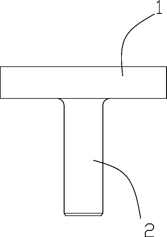
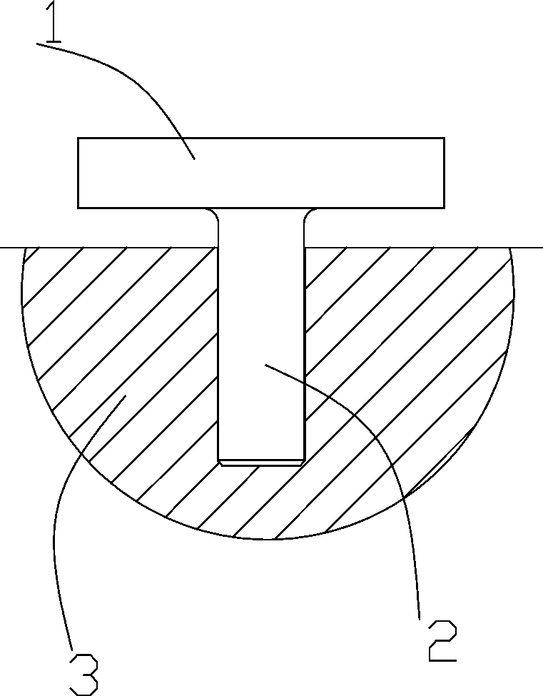
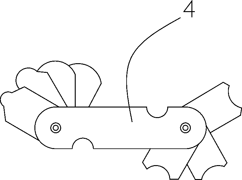
[0012] see Figure 1 to Figure 3 As shown, a kind of internal chamfering detection device comprises a handle 1, on which a cylindrical measuring rod 2 made of metal tin is arranged, and the measuring rod 2 is inserted into the recess of the part 3 to be detected and Fits inside chamfers; fillet gauge 4 also included. The present invention adopts metal tin with soft texture, low melting point and strong plasticity at normal temperature as the measuring rod 2, which is inserted into the depression of the part to be detected, so that the front end of the measuring rod is pressed into an outer chamfer with consistent inner chamfering, The outer chamfer is then directly measured without being limited by the variation of the aperture.

[0013] The aforementioned inner chamfers include inner chamfers and inner rounded corners.

[0014] In...


PUM


Abstract

The invention discloses an inner chamfer detection device and method, and belongs to the technical field of detection. The inner chamfer detection device comprises a handle. A measuring rod made of metallic tin is arranged on the handle. The measuring rod is inserted into the sunken portion of a part to be detected and attached to an inner chamfer. The inner chamfer detection method comprises the following steps of firstly fixing the part to be detected, inserting the measuring rod made of the metallic tin into the sunken portion of the part to be detected so that the front end of the measuring rod can be pressed to form an outer chamfer consistent with the inner chamfer, pulling out the measuring rod, using a fillet gauge for detecting the outer chamfer formed at the front end of the measuring rod, judging whether relative reading is within the allowable tolerance range of the size of the inner chamfer or not, and continuously and circularly conducting rapid detection on the inner chamfer of a next part to be detected. Compared with the prior art, the front end of the measuring rod is pressed to form the outer chamfer consistent with the inner chamfer, the outer chamfer is directly measured, limitation caused by aperture changes does not exist, and meanwhile the inner chamfer detection device has the advantages of being simple in structure, convenient to use and operate, free of space limitation and the like.

Description

technical field [0001] The invention belongs to the technical field of detection, and in particular relates to an inner chamfering detection device and a detection method. Background technique [0002] In the machining industry, the chamfering of holes can be seen everywhere. One uses a caliper or a projector to detect the chamfering depth of the hole. However, the caliper cannot be correctly positioned on the chamfering slope, resulting in inaccurate detection results. The shadow instrument is limited by space. It cannot be detected in a small space. The above problems need to be solved urgently. Contents of the invention [0003] Aiming at the deficiencies in the prior art, the invention provides an inner chamfering detection device and a detection method. [0004] In order to solve the above-mentioned technical problems, the present invention is solved by the following technical solutions: a kind of internal chamfer detection device, comprising a handle, on which a cy...

Claims


Application Information

Patent Timeline
Patent Type & Authority Applications(China)
IPC IPC(8): G01B5/24
Inventor 韩剑敏
Owner YUYAO CITY ZHENXING IND TRADE DEV
Learn More