Flap twist test system

A technology of twist testing and flaps, which is applied in the field of flap twist testing systems, can solve problems such as complex interfaces, and achieve the effects of reducing complexity, reducing volume, and reducing the number of interfaces

Inactive Publication Date: 2014-08-06
XIAN AIRCRAFT DESIGN INST OF AVIATION IND OF CHINA
View PDF7 Cites 9 Cited by
  • Summary
  • Abstract
  • Description
  • Claims
  • Application Information

AI Technical Summary

Problems solved by technology

[0005] The technical problem to be solved in the present invention is: for the conventional layout transport aircraft flap system, that is: each 2 flap rudder surfaces on the left and right, each flap rudder surface has two ball screw screws, and each flap rudder surface is passed through The power drive device located in the center of the wing drives the flap torque transmission line to control the flap movement, provides a flap twist test system, solves the interface complex problem caused by conventional design, and simplifies the design of the flap control system controller. Thus saving cost while improving system reliability and optimizing system design

Method used


Image

  • Flap twist test system
  • Flap twist test system
  • Flap twist test system

Examples


Embodiment Construction

[0025] The present invention will be further described below in conjunction with the accompanying drawings.

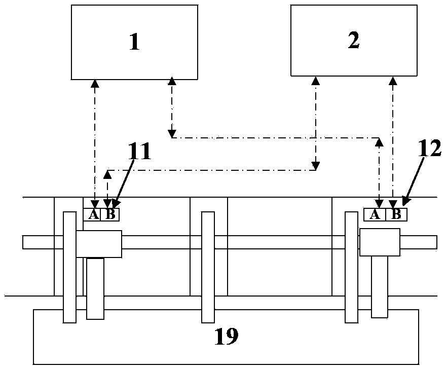
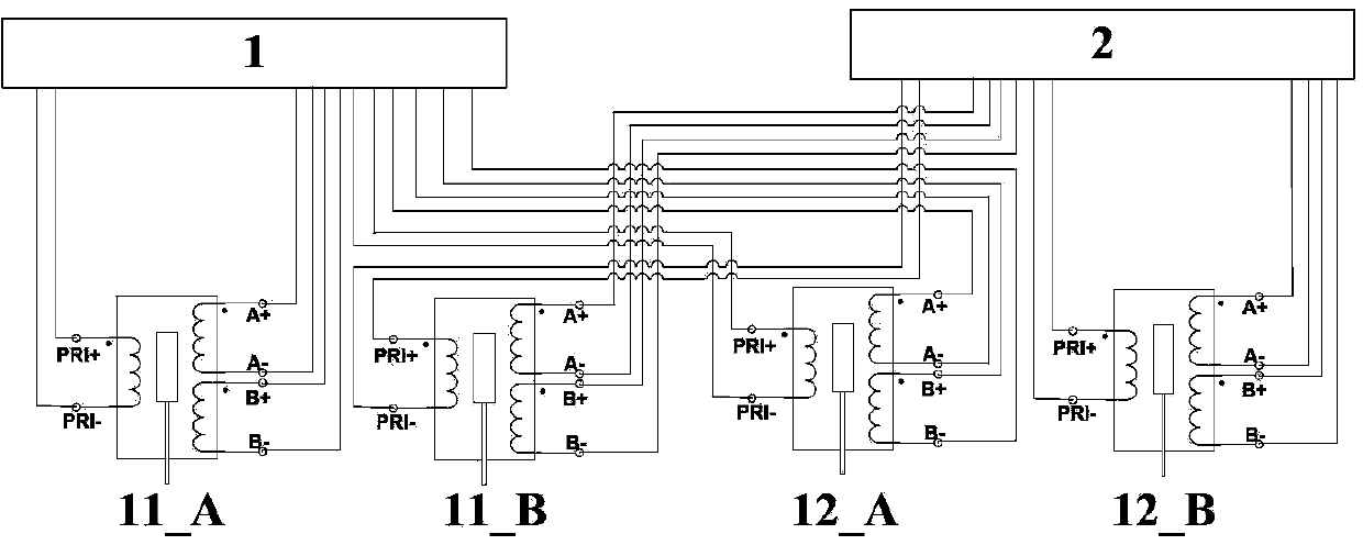
[0026] join Figure 4 , a flap twist test system, including a left controller 1, a left controller 2, a left ball screw 3, a left ball screw 4, a left ball screw 5, a left ball screw 6, a right four Ball screw 7, right third ball screw 8, right second ball screw 9, right first ball screw 10, left first flap twist sensor 11, left second flap twist sensor 12, left third flap twist sensor 13, Left 4th flap distortion sensor 14, right 4th flap distortion sensor 15, right 3rd flap distortion sensor 16, right 2nd flap distortion sensor 17, right 1st flap distortion sensor 18, left 1st flap 19, left 2nd flap 20. The second right flap 21 and the first right flap 22; the eight flap twist sensors are all linear variable differential transformers with two electrical redundancy in channel A and channel B, wherein,

[0027] The primary side of channel A of the first left flap twi...


PUM


Abstract

The invention belongs to the technical field of monitoring of flight control systems, and relates to a flap twist test system. The signal change reversible principle of LVDTs is utilized, when a twist test is conducted on each control plane, the LVDTs on two ball screws on each control plane are connected in series and then connected to a controller, in other words, the auxiliary sides of the LVDTs corresponding to every two ball screws are connected, and the primary sides of the LVDTs are connected to the controller. Through the method, the number of interfaces of the LVDTs connected to the controller is greatly reduced, so that the design of a hardware circuit of the controller is simplified, complexity of the controller is reduced, the size and the weight of the controller are reduced, reliability of the controller is improved, and meanwhile the number of onboard cables is reduced.

Description

technical field [0001] The invention belongs to the technical field of flight control system monitoring, and relates to a flap twist testing system. Background technique [0002] Transport aircraft mostly use flaps and slats as the function of increasing lift during take-off and increasing lift and increasing resistance during landing, and generally speaking, the driving power sources of these flaps and slats are located in the The torsion tubes at the front and rear edges of the wing are transmitted to the slats or flaps, and these torsion tubes bear a large load. If the control system still controls the output when a certain part of the rudder drive is blocked, the torsion tube will inevitably break; or Due to factors such as aging, corrosion, long-term wear and tear plus a large torsional moment, the middle of the torque tube is broken. Since the use of flaps and slats is in the dangerous stages of take-off and landing, the breakage of the torsion tube without protection...

Claims


Application Information

Patent Timeline
Patent Type & Authority Applications(China)
IPC IPC(8): G01M13/00
Inventor 杜永良
Owner XIAN AIRCRAFT DESIGN INST OF AVIATION IND OF CHINA
Why Eureka
Try Eureka