Supercharge Your Innovation With Domain-Expert AI Agents!

Locomotive wheelset connecting rod pin crack ultrasonic probe

A connecting rod pin and ultrasonic technology, applied in the field of probes, can solve the problem that the crack defect of the connecting rod pin cannot be effectively detected, the in-service online detection, real-time tracking and monitoring of the connecting rod pin of the locomotive wheelset cannot be realized, and the locomotive wheelset cannot be detected. Connecting rod pin crack defects and other problems, to achieve the effect of shortening the maintenance cycle, improving reliability and safety, and simple structure

Active Publication Date: 2014-08-06
CSR CHENGDU
View PDF5 Cites 4 Cited by
  • Summary
  • Abstract
  • Description
  • Claims
  • Application Information

AI Technical Summary

Problems solved by technology

[0005] 1. It can only detect surface crack defects of locomotive wheel set connecting rod pins in a single and independent state, and cannot detect crack defects of locomotive wheel set connecting rod pins in assembled and undisassembled states;
[0006] 2. In-service online detection, real-time tracking and monitoring of locomotive wheel set connecting rod pins cannot be realized
It is feasible and effective to use the magnetic particle inspection method for the connecting rod pin in a single piece, independent and exposed state; however, it is not a single piece, independent and in the In the online state of service, since the detection part of the connecting rod pin is not visible to the naked eye, that is, the detection part is not exposed, the crack defect of the connecting rod pin cannot be effectively detected by using the existing ultrasonic probe to detect the crack of the connecting rod pin of the locomotive wheel

Method used


Image

  • Locomotive wheelset connecting rod pin crack ultrasonic probe
  • Locomotive wheelset connecting rod pin crack ultrasonic probe

Examples


Embodiment Construction

[0026] The present invention will be further described below in conjunction with specific examples.

[0027] All features disclosed in this specification, or steps in all disclosed methods or processes, except for mutually exclusive characteristics and / or steps, can be combined in any way, unless otherwise stated, they can be used by other equivalent or similar Instead, each feature is intended to be replaced by alternative features, that is, each feature is only one embodiment of a series of equivalent or similar features unless stated otherwise.

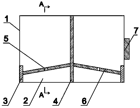
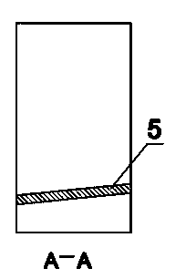
[0028] Such as figure 1 , 2 As shown, the ultrasonic probe for cracks in the connecting rod pin of the locomotive wheel set of the present invention includes two plexiglass delay blocks 2 , a sound insulation layer 4 and two dual crystal probes 6 with flaw detection wafers 5 . The sound insulation layer 4 is vertically arranged in the middle of the two plexiglass delay blocks 2, and the flaw detection chip with the transmitting e...


PUM

PropertyMeasurementUnit
thicknessaaaaaaaaaa
thicknessaaaaaaaaaa
thicknessaaaaaaaaaa

Abstract

The invention discloses a locomotive wheelset connecting rod pin crack ultrasonic probe. The locomotive wheelset connecting rod pin crack ultrasonic probe comprises two organic glass delay blocks, a sound insulation layer and two double-crystal probes with flaw detection chips, wherein the sound insulation layer is vertically arranged between the two organic glass delay blocks; the flaw detection chip with an emission end and the flaw detection chip with a receiving end are respectively arranged on the double-crystal probes on two sides of the sound insulation layer; two ferromagnets are attached to both sides of the organic glass delay blocks; the organic glass delay blocks, the sound insulation layer and the ferromagnets are encapsulated in a probe shell; a connector is arranged on one side of the probe shell. The locomotive wheelset connecting rod pin crack ultrasonic probe realizes crack flaw detection of a locomotive wheelset at a single independent finished product state and an assembling state (namely, non-individual, independent and un-disassembly state, i.e. non-detachable overhauling), as well as in-service online detection, real-time tracking and monitoring of connecting rod pins, and the quality of products is improved.

Description

technical field [0001] The invention relates to a probe, in particular to an ultrasonic probe for cracks in a locomotive wheel pair connecting rod pin, belonging to the technical field of probes. Background technique [0002] At present, the non-destructive testing of the connecting rod pins of domestic locomotive wheels is to use magnetic particle testing to detect defects on the surface of the connecting rod pins when they are not assembled or disassembled, that is, in a single and independent state. [0003] The technical requirements for the product drawings of the connecting rod pin of the locomotive wheel set are: to conduct magnetic particle inspection on the surface of the connecting rod pin, and cracks are not allowed. The existing non-destructive testing process for connecting rod pins is to perform magnetic particle inspection on the detection parts in the state of a single and independent finished product of the connecting rod pins, and can only detect crack de...

Claims


Application Information

Patent Timeline
Patent Type & Authority Applications(China)
IPC IPC(8): G01N29/24
Inventor 王蔚明王瑶周建孔琦
Owner CSR CHENGDU
Features
  • R&D
  • Intellectual Property
  • Life Sciences
  • Materials
  • Tech Scout
  • Unparalleled Data Quality
  • Higher Quality Content
  • 60% Fewer Hallucinations
Learn More