
Three-dimensional scanning acoustic imaging device

A technology of imaging device and three-dimensional scanning, which is applied in the direction of measurement device, sound wave re-radiation, utilization of re-radiation, etc. Novel, overall complexity and cost reduction, high-tech effects

Inactive Publication Date: 2014-08-06
BEIJING HYDRO TECH MARINE TECH CO LTD
View PDF7 Cites 7 Cited by
  • Summary
  • Abstract
  • Description
  • Claims
  • Application Information

AI Technical Summary

Problems solved by technology

The traditional method uses divers to detect underwater structures. This method is extremely inefficient, and there are many safety hazards in underwater operations for divers.
[0003] With the development of science and technology, more and more underwater detection is carried out by side-scan sonar and multi-beam bathymetric sonar. However, side-scan sonar is mainly displayed in the form of images, and it is difficult to give a specific three-dimensional structure. Underwater search and rescue, pipeline detection and other applications that only use image information; although the multi-beam echo sounder can give the underwater three-dimensional structure, but the main purpose of the multi-beam echo sounder is underwater surveying and mapping, so it is difficult to analyze bridge piers, ocean Platforms and other structures perpendicular to the bottom of the water for three-dimensional imaging, especially near the water surface, the multi-beam echo sounder is basically unable to measure

Method used


Image

  • Three-dimensional scanning acoustic imaging device
  • Three-dimensional scanning acoustic imaging device
  • Three-dimensional scanning acoustic imaging device

Examples


Embodiment Construction

[0021] Specific implementation plan

[0022] The present invention will be further described below with reference to the drawings and a preferred embodiment of the present invention.

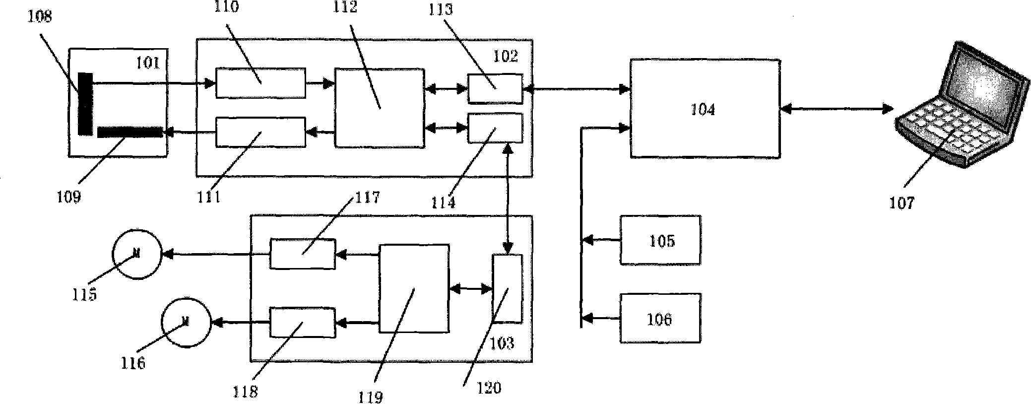
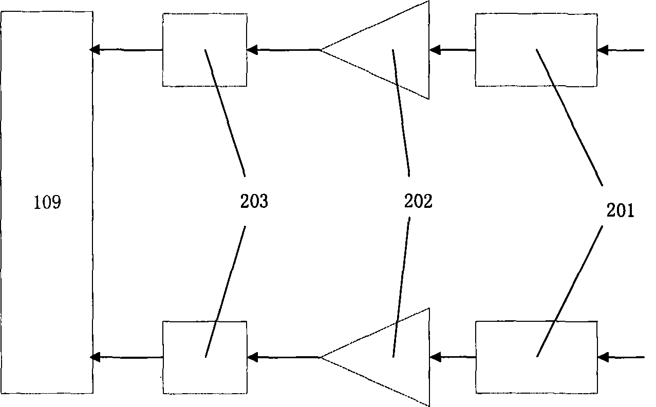
[0023] As a preferred embodiment of the present invention, the three-dimensional scanning acoustic imaging device has an acoustic center operating frequency of 800KHz, and the multi-element linear receiving transducer array (203) and multi-element linear transmitting transducer array (203) both use 64 Element linear array structure, thereby forming a 120°x1° acoustic emission beam and a 1°x15° acoustic receiving beam.

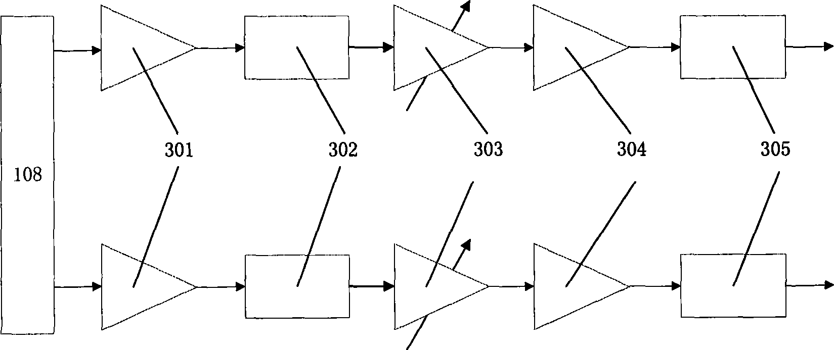
[0024] As a preferred embodiment of the present invention, all the electronic parts of the acoustic signal conversion unit (102) and the signal processing unit (104) are placed in a watertight cabin. The casing of the sealed cabin is made of 316 stainless steel. The energy sensor array (108) and the multi-element linear transmitting transducer array (109) are fixed on the watertight ho...


PUM


Abstract

The invention discloses a three-dimensional scanning acoustic imaging device and belongs to the field of underwater engineering mapping, and particularly the three-dimensional scanning acoustic imaging device is composed of an underwater machine rotary table, an acoustic imaging unit and an auxiliary measuring device. An acoustic multi-beam ranging principle is adopted as the basic principle of the device, a transmitting transducer array transmits sound beams which are narrow in the horizontal direction and wide in the perpendicular direction to irradiate a detection area, the transmitting transducer array conducts beam forming processing on received multi-channel signals to form multiple receiving beams which are quite narrow in the perpendicular direction, the arriving time of the echo of each receiving beam is calculated, the position of a space target can be calculated according to the direction of the beams, one perpendicular scanning line of an underground scene can be obtained through each time of receiving and transmitting, 360-degree rotary scanning is conducted on the horizontal plane through the underwater machine rotary table, finally, a three-dimensional point cloud image of the specific underwater area is formed, and therefore a three-dimensional structure of the underwater scene is visually reflected. The device can be widely applied to multiple fields of underwater structural object detection, bridge underwater detection, ocean platform underwater safety monitoring and the like.

Description

Technical field [0001] The present invention relates to the fields of underwater engineering and underwater surveying and mapping. More specifically, it relates to a three-dimensional scanning acoustic imaging device, which is widely used in underwater structure detection, bridge underwater detection, marine platform underwater safety monitoring, etc. Areas. Background technique [0002] Large underwater structures, such as bridge piers, piers, ocean platforms, offshore buildings, etc., after a long period of time in the water, due to the erosion and erosion of water currents, a large number of safety hazards such as damage and deformation will occur. The traditional method uses divers to detect underwater structures. This method is extremely inefficient. At the same time, there are many hidden safety hazards for divers underwater operations. [0003] With the development of science and technology, more and more underwater inspections are performed using side scan sonar, multi-bea...

Claims


Application Information

Patent Timeline
IPC IPC(8): G01S15/89
CPCG01S7/521G01S15/06G01S15/86G01S15/89
Inventor 么彬殷敬伟张晓韩笑曲海峰李春笛
Owner BEIJING HYDRO TECH MARINE TECH CO LTD
Learn More