
Dynamic aging method for smectic liquid crystal display

A liquid crystal display and dynamic aging technology, applied in static indicators, nonlinear optics, instruments, etc., can solve the problems of poor aging effect, low aging efficiency, and long aging time, so as to improve the aging effect and accelerate the aging speed , Improve the effect of aging efficiency

Inactive Publication Date: 2014-08-06
HALATION PHOTONICS CORP
View PDF7 Cites 4 Cited by
  • Summary
  • Abstract
  • Description
  • Claims
  • Application Information

AI Technical Summary

Problems solved by technology

However, it can be found from actual implementation that the voltage amplitude and frequency of the pulses applied when the existing aging method changes the full screen to a fully transparent state (screen clearing operation) or a foggy light-proof state (scrubbing operation) are fixed, After the pulse is applied, the display screen needs to last for a long time to stabilize the characteristics of the smectic liquid crystal and achieve the purpose of aging. It can be seen that the existing aging methods have the disadvantages of long aging time, low aging efficiency, and poor aging effect. problem to be solved

Method used

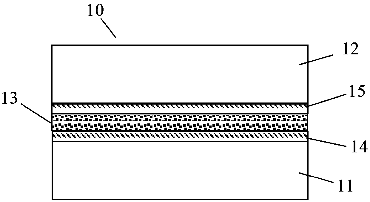
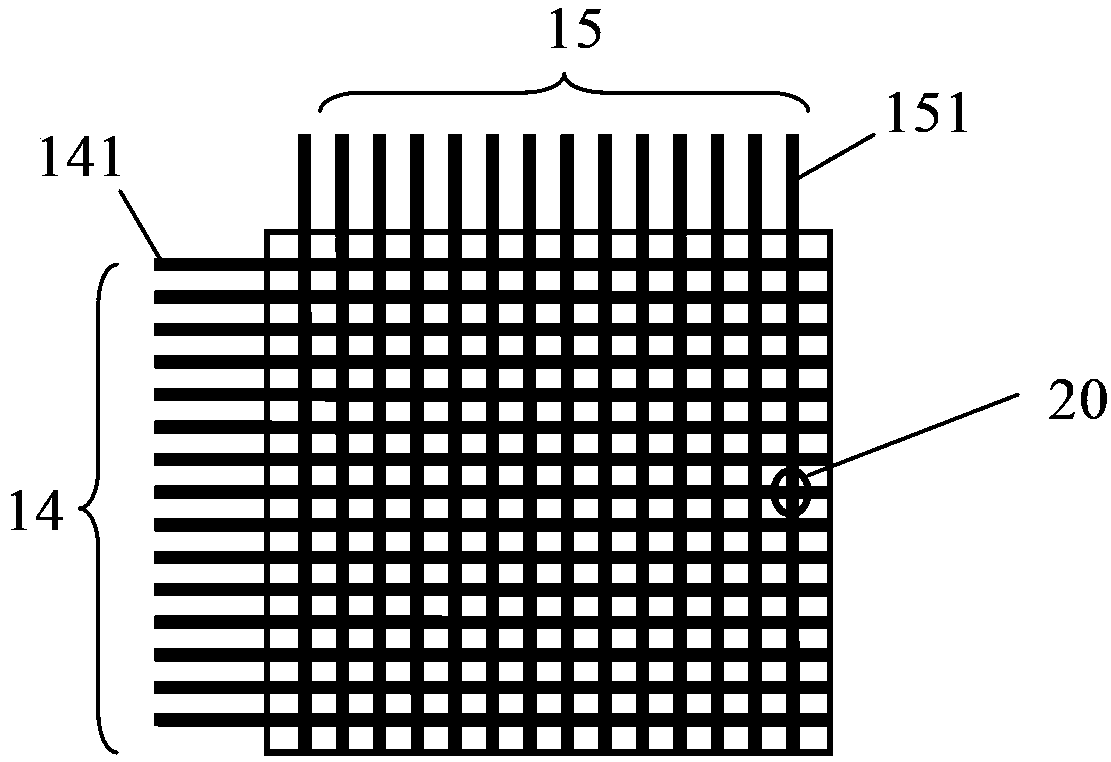

Image

  • Dynamic aging method for smectic liquid crystal display
  • Dynamic aging method for smectic liquid crystal display
  • Dynamic aging method for smectic liquid crystal display

Examples


no. 1 example

[0060]In the first embodiment, a pair of low-frequency pulse signals applied to the row and column electrodes in the full-screen dynamic scrubbing operation is as follows: Figure 4A shown. exist Figure 4A Among them, the waveform diagram above is the low-frequency pulse signal applied on the row electrode, the low-frequency pulse signal is composed of x pulse groups, the number of pulse pairs in the first pulse group is Nf1, and the number of pulse pairs in the second pulse group Nf2,..., the number of pulse pairs in the last pulse group is Nfx, that is, the number of pulse pairs in each pulse group is different, the voltage amplitude of each pulse group is Um, and the frequency of each pulse group is different, the first The frequency of the first pulse group is 1 / Tf1, the frequency of the second pulse group is 1 / Tf2, ..., the frequency of the last pulse group is 1 / Tfx, Tf1>Tf2>...>Tfx. exist Figure 4A Among them, the waveform diagram below is the low-frequency pulse si...

no. 2 example

[0064] In the second embodiment, a pair of low-frequency pulse signals applied to the row and column electrodes in the full-screen dynamic scrubbing operation is as follows: Figure 5A shown. exist Figure 5A Among them, the above waveform diagram is the low-frequency pulse signal applied on the row electrodes. The low-frequency pulse signal is composed of x pulse groups. is 1 / Tf, and the voltage amplitude of each pulse group is different, the voltage amplitude of the first pulse group is UR1, the voltage amplitude of the second pulse group is UR2,..., the voltage amplitude of the last pulse group For URx, UR1>UR2>...>URx. exist Figure 5A Among them, the waveform diagram below is the low-frequency pulse signal applied on the column electrodes. The phase of the low-frequency pulse signal is opposite to that of the low-frequency pulse signal applied on the row electrodes, and the voltage amplitude of the waveform is different as a whole. Specifically, the low-frequency pulse...


PUM


Abstract

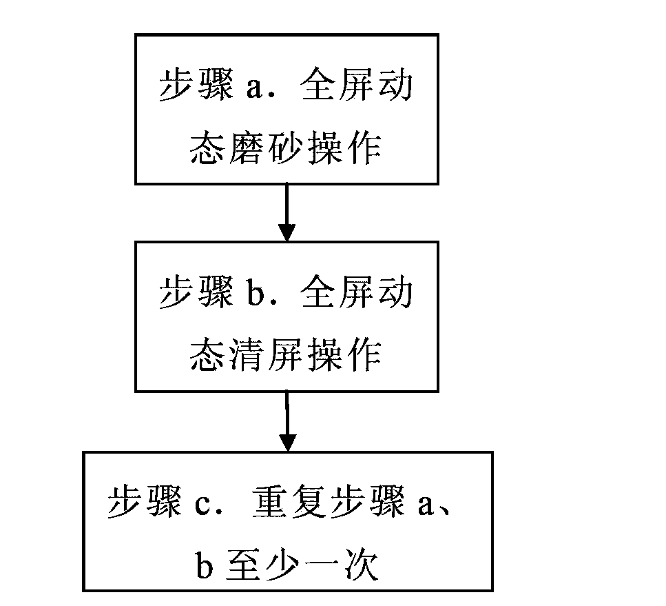
The invention discloses a dynamic aging method for a smectic liquid crystal display. The method comprises the step of repeating full-screen dynamic frosting operation and full-screen dynamic screen clearing operation at least once. According to the method, the frequency and / or voltage amplitude of low-frequency pulse signals applied to row and column electrodes in dynamic frosting operation are / is dynamically changed according to actual conditions, and the frequency and / or voltage amplitude of high-frequency pulse signals applied to the row and column electrodes in dynamic screen clearing operation are / is dynamically changed, so that smectic liquid crystals can rapidly tend to be stable within a short time, and the smectic liquid crystal display can be rapidly aged; compared with a conventional aging method, the method provided by the invention has the advantages that the aging speed is increased, the aging time is shortened, the aging efficiency is improved, and aging effects are improved.

Description

technical field [0001] The invention relates to an aging method for a smectic liquid crystal display, in particular to an aging method for dynamically adjusting voltage amplitude and / or frequency applied to a smectic liquid crystal display, and belongs to the aging field of a smectic liquid crystal display . Background technique [0002] Liquid crystal display is one of the most promising flat panel display devices at present. Traditional liquid crystal displays are passive displays, that is, transmissive displays, which can only be displayed under the condition of an external backlight, but the power consumption of the backlight is the liquid crystal itself. More than hundreds of times the power consumption, very energy-consuming. With the development of liquid crystal technology, various liquid crystal materials emerge in an endless stream, among which the reflective liquid crystal that does not require a backlight has an absolute advantage due to its low power consumptio...

Claims


Application Information

Patent Timeline
IPC IPC(8): G02F1/13G09G3/36
Inventor 任宇余江孙刚夏兴隆
Owner HALATION PHOTONICS CORP
Learn More