
A power amplifier unit deployment method for a power amplifier array

A technology of input matrix and output matrix is ​​applied in the field of power amplifier unit deployment of power amplifier array to achieve the effect of improving fault self-detection, improving stability and maintainability

Active Publication Date: 2017-08-08
广州市迪士普音响科技有限公司
View PDF3 Cites 0 Cited by
  • Summary
  • Abstract
  • Description
  • Claims
  • Application Information

AI Technical Summary

Problems solved by technology

[0003] In many important places such as subways, airports, gymnasiums and other sound reinforcement engineering fields, the sound system needs to work continuously without interruption, which puts forward higher requirements for the trouble-free rate of the sound system. The traditional power amplifier working mode has been difficult to meet this requirement. kind of demand

Method used


Image

  • A power amplifier unit deployment method for a power amplifier array
  • A power amplifier unit deployment method for a power amplifier array
  • A power amplifier unit deployment method for a power amplifier array

Examples


no. 1 Embodiment

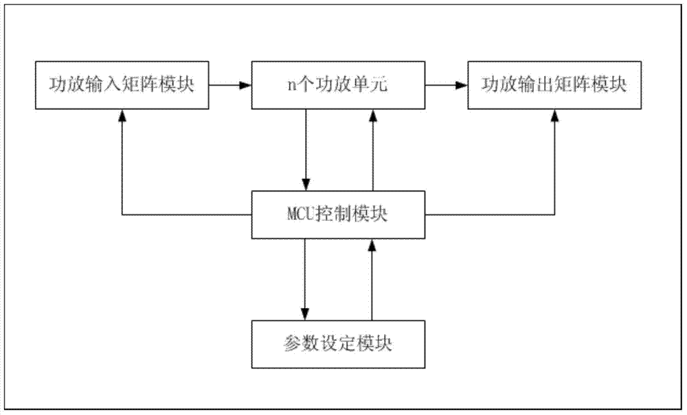
[0026] refer to figure 1 , the first specific embodiment of the present invention, a system applying the power amplifier allocation method of the power amplifier array of the present invention, including a power amplifier input matrix module, n power amplifier units, a power amplifier output matrix module, an MCU control module and a parameter control module, the The first output end of the MCU control module is connected to the control end of the power amplifier input matrix module, the second output end of the MCU control module is connected to the control end of the power amplifier output matrix module, and the parameter control module is connected to the power amplifier through the MCU control module. n power amplifier units, the output terminals of the power amplifier input matrix module are connected to the input terminals of the n power amplifier units, and the output terminals of the n power amplifier units are connected to the input terminals of the power amplifier out...


PUM


Abstract

The invention discloses a power amplifier unit allocation method of a power amplifier array, which comprises the following steps: A. Using an MCU control module to monitor the working state parameters of each power amplifier unit; B. According to the monitoring result, the MCU control module inputs the power amplifier through a program instruction The audio channel of the matrix module is adjusted to point to the spare power amplifier unit, and the power amplifier output matrix module is controlled to output the audio signal to the designated channel, so as to complete the allocation of the power amplifier array in a coordinated manner. The present invention adopts the power amplifier unit allocation method of the above-mentioned power amplifier array, and improves the system fault self-detection and self-adaptive functions through real-time monitoring of the working status of each power amplifier unit of the power amplifier array. When a certain power amplifier unit fails, the system will automatically cut off the power amplifier. Units, call idle or low-level power amplifier units; improve the stability, reliability and maintainability of the power amplifier array system. As a power amplifier unit allocation method of the power amplifier array, the invention can be widely used in the field of power amplifiers.

Description

technical field [0001] The invention relates to the field of audio power amplifiers, in particular to a method for allocating power amplifier units of a power amplifier array. Background technique [0002] In the audio system, the power amplifier is responsible for the task of power amplification and needs high voltage and high current to drive the work, which is the weak link of the audio system. The user's audio system may use multiple power amplifiers at the same time. Traditionally, multiple masters and one backup are used to ensure the reliability of the power amplifier. The power amplifier needs to be interrupted during the replacement process. After the only backup power amplifier is enabled, if other main power amplifiers or backup power amplifiers fail, there will be no other power amplifiers to replace. [0003] In many important places such as subways, airports, gymnasiums, etc., the audio system needs to work continuously without interruption, which puts forward...

Claims


Application Information

Patent Timeline
Patent Type & Authority Patents(China)
IPC IPC(8): H04R29/00H04R27/00
Inventor 王齐祥
Owner 广州市迪士普音响科技有限公司
Learn More