Light-emitting diode drive circuit

A technology of light-emitting diodes and driving circuits, which is applied to the layout of electric lamp circuits, light sources, electric light sources, etc., can solve the problem that the current error is not enough to meet the high-quality display, and achieve the effect of reducing the bias error

Active Publication Date: 2014-08-06
PRINCETON TECHNOLOGY
View PDF3 Cites 0 Cited by
  • Summary
  • Abstract
  • Description
  • Claims
  • Application Information

AI Technical Summary

Problems solved by technology

Therefore, only improving the current error between ICs is not

Method used


Image

  • Light-emitting diode drive circuit
  • Light-emitting diode drive circuit

Examples


Embodiment Construction

[0015] The following is an introduction to the preferred embodiments of the present invention. Each embodiment is used to illustrate the principle of the present invention, but not to limit the present invention. The scope of the invention should be determined by the appended claims.

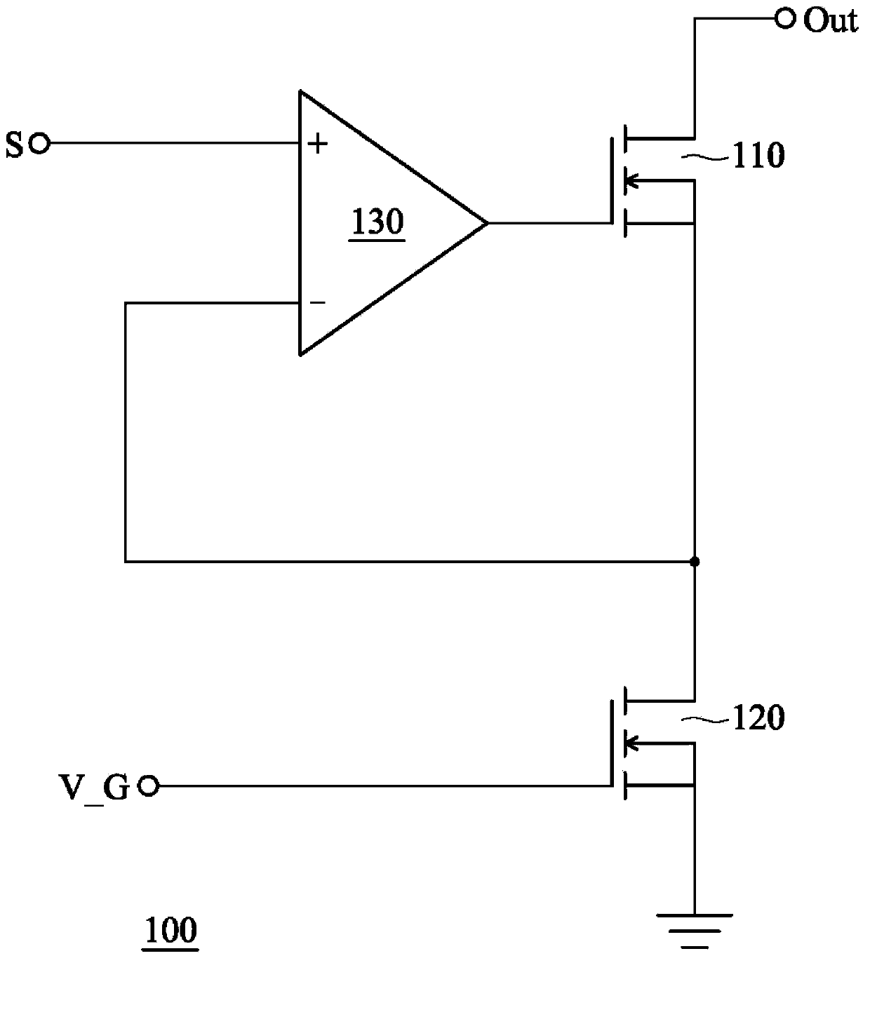
[0016] figure 1 It is a circuit structure diagram of a driving circuit of a light emitting diode (LED). In this figure, the LED driving circuit 100 includes an output NMOS (N channel Metal-Oxide-Semiconductor Field-Effect Transistor, NMOS) transistor 110 , a grounded NMOS transistor 120 , and an operational amplifier 130 . The output NMOS transistor 110 has a drain connected to the output terminal Out and a source connected to the drain of the grounded NMOS transistor 120 in series, wherein the output terminal Out is further connected to an LED (not shown). The grounded NMOS transistor 120 receives the bias voltage V_G with a gate and grounded with a source. The operational amplifier 130 can...


PUM


Abstract

A light-emitting diode drive circuit comprises an output transistor which is coupled to a light-emitting diode, a node which is coupled to the output transistor, a grounded transistor which is coupled to the node and grounded and an operational amplifier. The operational amplifier comprises an input stage which comprises a first input end and a second input end, an output stage and a first group switch which is used for providing a drive signal for one of the first input end and the second input end and connecting the node to the other one of the first input end and the second input end. The two input ends of the operational amplifier can receive the drive signals in turn so that the influence caused by bias errors of the operational amplifier can be reduced.

Description

technical field [0001] The present invention relates to a light-emitting diode driving circuit, and further includes a light-emitting diode driving circuit for suppressing luminance errors. Background technique [0002] In light emitting diode (LED) displays, luminance errors often occur between different modules due to variation in drive current across the LEDs. In addition, for a full-color display, when the driving current is inaccurate, color blocks are very likely to appear on the display screen, and the impact on the display quality is quite obvious. [0003] The luminance error can be divided into the current error between output channels and the current error between ICs. Among them, the current error between ICs is mainly caused by process drift between different manufacturing batches of ICs. Although process drift is unavoidable, most of the existing technology still improves on the current error between ICs. The causes of current errors between ICs are complex,...

Claims


Application Information

Patent Timeline
IPC IPC(8): H05B37/02
Inventor 曹铭原
Owner PRINCETON TECHNOLOGY
Why Eureka
Try Eureka