A method for selecting crystal oscillator of fiber optic gyroscope main control board based on anti-fuse fpga

A fiber optic gyroscope and anti-fuse technology, which is applied to Sagnac effect gyroscopes, gyroscopes/steering sensing equipment, measuring devices, etc. problem, to achieve the effect of high real-time performance, fast adjustment speed, and reduction of spurious frequency offset

Active Publication Date: 2017-05-31
BEIJING INST OF CONTROL ENG
View PDF5 Cites 0 Cited by
  • Summary
  • Abstract
  • Description
  • Claims
  • Application Information

AI Technical Summary

Problems solved by technology

[0006] The technical problem solved by the present invention is: to overcome the deficiencies in the prior art, to propose a method for selecting the crystal oscillator of the main control board of the fiber optic gyroscope based on the antifuse FPGA, and to solve the problem that the eigenfrequency design of the FPGA fiber optic gyroscope based on the antifuse is inaccurate and cause the gyro The problem of large zero deviation

Method used


Image

  • A method for selecting crystal oscillator of fiber optic gyroscope main control board based on anti-fuse fpga
  • A method for selecting crystal oscillator of fiber optic gyroscope main control board based on anti-fuse fpga
  • A method for selecting crystal oscillator of fiber optic gyroscope main control board based on anti-fuse fpga

Examples


Embodiment Construction

[0022] The present invention will be further described in detail below in conjunction with the accompanying drawings.

[0023] 1. Frequency offset error analysis caused by inaccurate modulation frequency

[0024] 1.1 Analysis of the situation that the modulation frequency is equal to the eigenfrequency

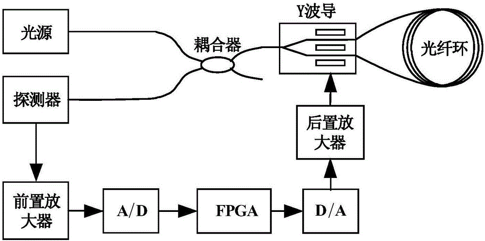
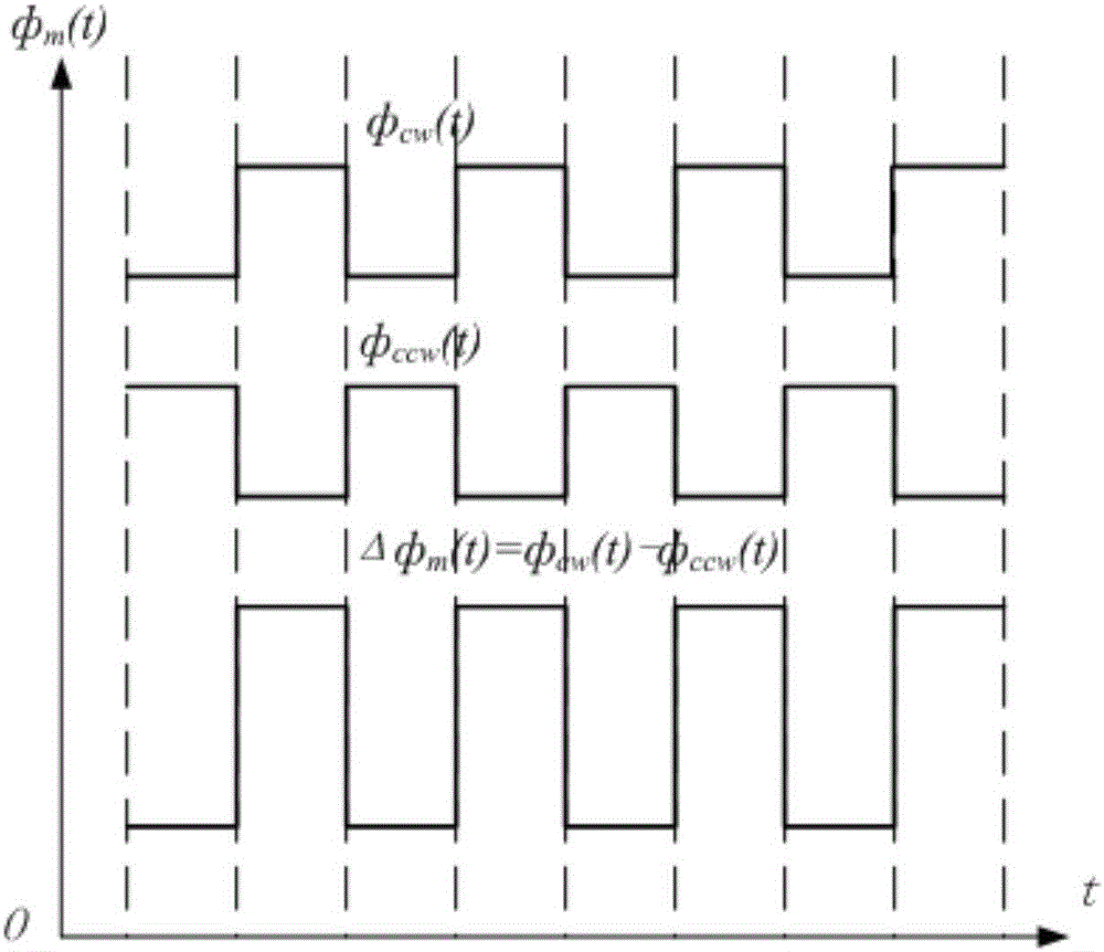
[0025] For the functional block diagram of the fiber optic gyroscope, see figure 1 shown. Due to LiNbO 3 The anisotropy of the crystal, the electro-optic effect is related to the direction of the electric field. When the modulation voltage V is applied between the positive pole and the negative pole m When (t), a pair of electric fields with opposite directions will be generated on the two arms of the Y branch waveguide, and the corresponding optical refractive index change Δn caused by the applied electric field is also opposite, that is, the phase change of the guided light in the two arm waveguides is also opposite. It is equivalent to applying two phase modulation sig...


PUM


Abstract

The invention provides a fiber-optic gyroscope main control panel crystal oscillator selecting method based on anti-fuse FPGA. The method comprises the following steps: (1) by virtue of an FPGA with a DDS (Direct Digital Synthesizer) module serving as a fiber-optic gyroscope control panel of a control chip, controlling the DDS module to generate the initial modulation frequency A; (2) observing the signal waveform of an output voltage of a photoelectric detector to determine whether the signal is a sharp comb periodic signal; (3) if not, controlling the DDS to generate modulation frequency B close to the modulation frequency A by the FPGA, repeating the above steps until the peak width reaches the dozens of ns magnitudes, considering to be equal to the eigen frequency of the gyroscope; and (4) amplifying the eigen frequency of the gyroscope by integer multiples of 2n to be used as the frequency of a selected crystal oscillator. The method can accurately measure the eigen frequency of the gyroscope, solves the problem of large zero offset of the gyroscope, caused by inaccurate eigen frequency design, and can provide reference for the anti-fuse-based FPGA crystal oscillator selection of a fiber-optic gyroscope main control panel.

Description

technical field [0001] The invention belongs to the field of inertial attitude sensor systems, and relates to a method for selecting a crystal oscillator of an optical fiber gyroscope main control board based on an antifuse FPGA. Background technique [0002] Interferometric fiber optic gyro is a sensor for measuring angular rate, and its hardware includes light source, coupler, Y waveguide, fiber optic ring, detector and signal processing device. Described signal processing device comprises the preamplifier that is used to detect the optical power signal that detector outputs, A / D converter, central processing unit FPGA, D / A converter and post amplifier form, as figure 1 shown. The measurement of the angular velocity of the interferometric fiber optic gyroscope is characterized by the size of the non-reciprocal phase difference caused by the two beams of light propagating in the fiber optic ring in the rotation of the fiber optic gyroscope itself. Gyroscopes are devices s...

Claims


Application Information

Patent Timeline
Patent Type & Authority Patents(China)
IPC IPC(8): G01C19/72
CPCG01C19/721
Inventor 林松赵亚飞孙丽
Owner BEIJING INST OF CONTROL ENG
Why Eureka
Try Eureka