Cellular emergency lighting management system

An emergency lighting and management system technology, applied to lighting devices, light sources, electric light sources, etc., can solve the problems of detection system paralysis, signal interference, time and manpower constraints, etc., to improve accuracy and stability, and avoid detection results deviation, the effect of improving stability and continuity

Inactive Publication Date: 2014-08-06
WISECON TECH COMPANY
View PDF7 Cites 2 Cited by
  • Summary
  • Abstract
  • Description
  • Claims
  • Application Information

AI Technical Summary

Problems solved by technology

Existing detection technology includes regular detection and maintenance of emergency lights on each floor of each building. The disadvantage of this is that it is limited by time and manpower, and it is impossible to obtain the real-time and accurate status of the entire lighting system. In good working order and without regular inspection reports
[0003] Another method needs to be tested in a wired way, without artificially checking the emergency lights on each floor, but this method needs to open a lot of wire slots on the building and set up more cables to connect All emergency lights not only need to destroy the structure of the wall, but also increase a lot of costs
None of these methods can be detected in real time, and cannot be automatically detected without unmanned operation, and the cost is very high
[0004] Based on this, wireless-based detection came into being. For example, Chinese patent 200580046582.6 proposes a central test radio frequency system for emergency lighting, which uses radio frequency communication to control emergency lighting units / emergency Lighting, it needs to connect all the emergency lights of the building into a communication network, and then perform wireless control at the remote end. Its advantage is that it gets rid of the old detection mode and uses radio frequency for detection; but based on its network Connection mode, each signal will interfere with each other, making the detection result inaccurate; and if one of the points fails, the entire detection system will be paralyzed, which will inevitably affect the operation of the detection

Method used


Image

  • Cellular emergency lighting management system
  • Cellular emergency lighting management system
  • Cellular emergency lighting management system

Examples


Embodiment Construction

[0031] In this article, the term "cellular" refers to a way of wireless communication, which is similar to the principle of mobile phone communication, that is, each communication node in the network system performs its own communication without affecting each other.

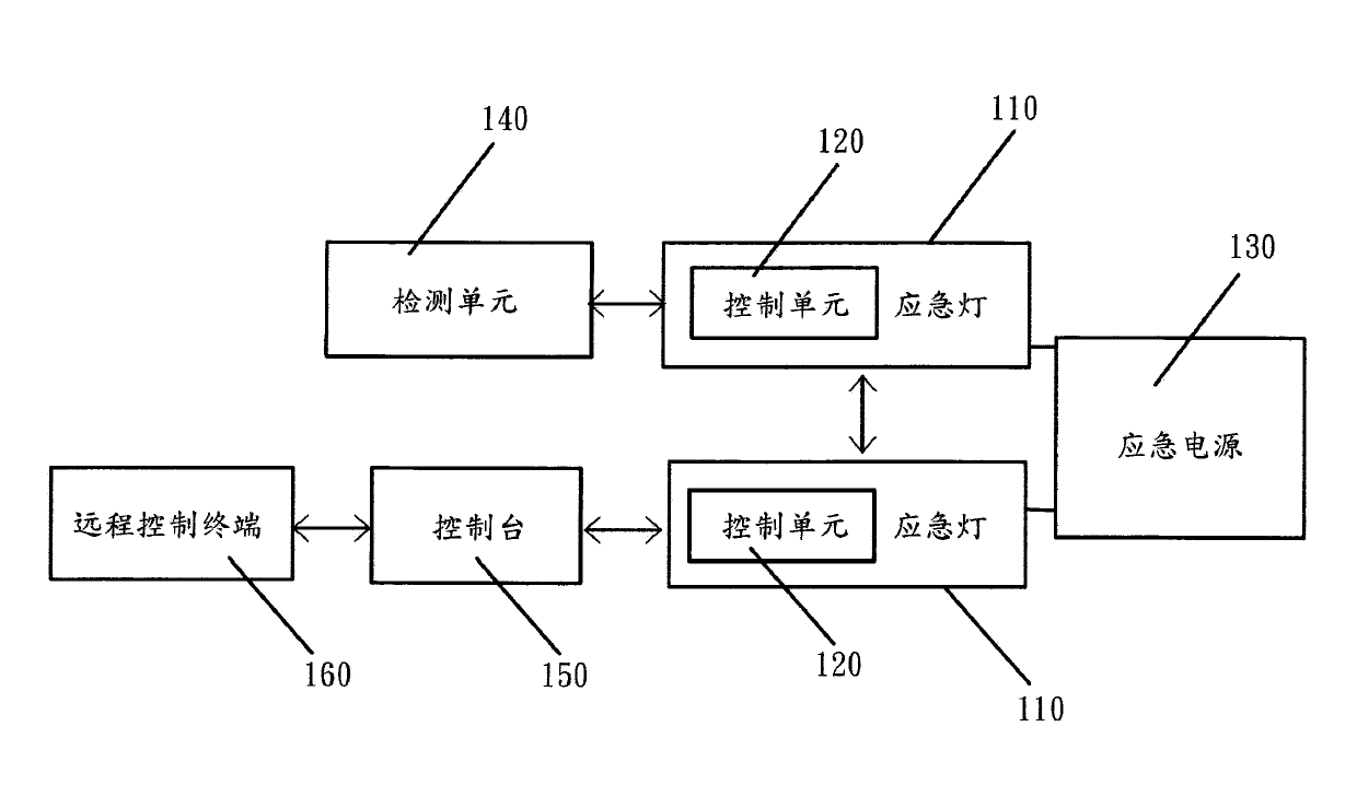
[0032] like figure 1 As shown, the cellular emergency lighting management system according to the present invention includes an emergency light 110 , a control unit 120 , an emergency power supply 130 , a detection unit 140 , a console 150 and a remote control terminal 160 .

[0033] There are multiple emergency lights 110, which are installed in corridors or stairwells of buildings and / or buildings, or other places in buildings and / or buildings, for emergency lighting of floors or the entire building. The emergency lights 110 are connected to each other to form an intercommunicating network.

[0034] This system provides emergency power supply 130 for the emergency lights 110. According to actual needs, one em...


PUM


Abstract

The invention relates to a cellular emergency lighting management system which comprises multiple emergency lamps, an emergency power source, a detection unit, control units, a control panel and a remote control terminal. The detection unit is used for detecting fault state of the emergency lamps, the control units are arranged inside the emergency lamps respectively to control the detection unit to detect the emergency lamps in real time, the control panel independently communicates with each emergency lamp through a wireless network, and the remote control terminal communicates with the control panel to enable the control panel to independently communicated with each control unit through the wireless network and enable the remote control terminal to control the detection unit to detect each emergency lamp in real time so as to acquire the fault state of each emergency lamp. The cellular emergency lighting management system breaks through conventional detection methods, and mutual interference among signals of the emergency lamps is avoided, so that accuracy and stability in detection are improved, and detection efficiency is improved. The cellular emergency lighting management system is economical, practical and suitable for large-scale popularization.

Description

technical field [0001] The invention relates to the management of an emergency lighting system, in particular, the invention relates to a real-time management and detection of an emergency lighting system in a building in a wireless manner. Background technique [0002] As a public facility in a building, the emergency lighting system plays a pivotal role. Therefore, it is necessary to know regularly whether these emergency lighting lights are in a fault state. Existing detection technology includes regular detection and maintenance of emergency lights on each floor of each building. The disadvantage of this is that it is limited by time and manpower, and it is impossible to obtain the real-time and accurate status of the entire lighting system. In good working order with no regular inspection reports. [0003] Another method needs to be tested in a wired way, without artificially checking the emergency lights on each floor, but this method needs to open a lot of wire slots...

Claims


Application Information

Patent Timeline
Patent Type & Authority Applications(China)
IPC IPC(8): H05B37/02
Inventor 刘国强
Owner WISECON TECH COMPANY
Why Eureka
Try Eureka