
Drive part seal

A technology of sealing device and driving part, which is applied in the direction of lighting and heating equipment, furnace type, furnace components, etc., can solve the problems of equipment investment, short service life, high maintenance cost, etc., and achieve the effect of suppressing wear

Active Publication Date: 2016-04-06
浦项控股股份有限公司
View PDF6 Cites 0 Cited by
  • Summary
  • Abstract
  • Description
  • Claims
  • Application Information

AI Technical Summary

Problems solved by technology

However, this blast furnace method has problems in that raw material pretreatment facilities such as coking facilities or sintering facilities generate facility investment and considerable maintenance costs, and require other facilities for treating pollutants
[0008] However, although not shown in the drawings, in the case where the drive shaft of the screw feeder provided at the hopper of the lump manufacturing equipment of such molten iron manufacturing equipment is sealed, a sealing member such as an O-ring or the like only There is a problem that it is difficult to maintain the airtightness stably because it is in contact with the drive shaft to maintain airtightness
[0009] In particular, when the drive shaft of the screw feeder is connected to a drive source such as an external drive motor for rotational drive, considerable vibration (vibration) is generated to damage the sealing member, resulting in a very short service life and poor sealing performance. It is also insufficient, so the sealing member needs to be replaced frequently, so in this case, there are various problems such as reducing the driving efficiency of the screw feeder.

Method used


Image

  • Drive part seal
  • Drive part seal
  • Drive part seal

Examples


Embodiment Construction

[0043] Hereinafter, the present invention will be described in detail with reference to the drawings.

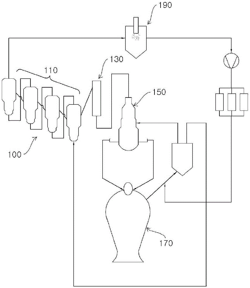
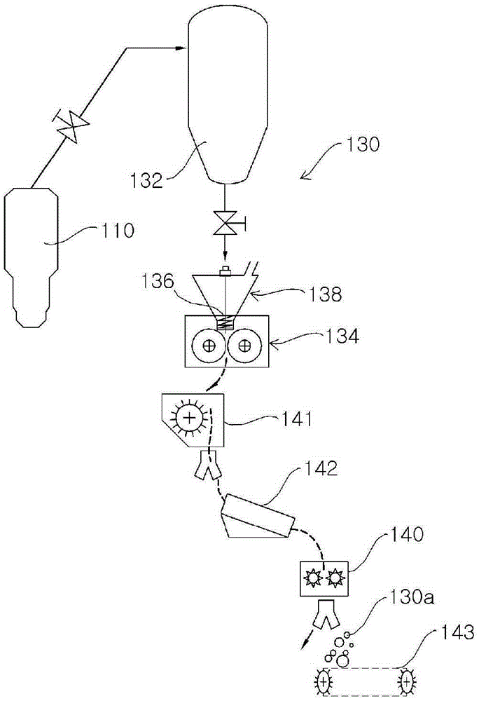
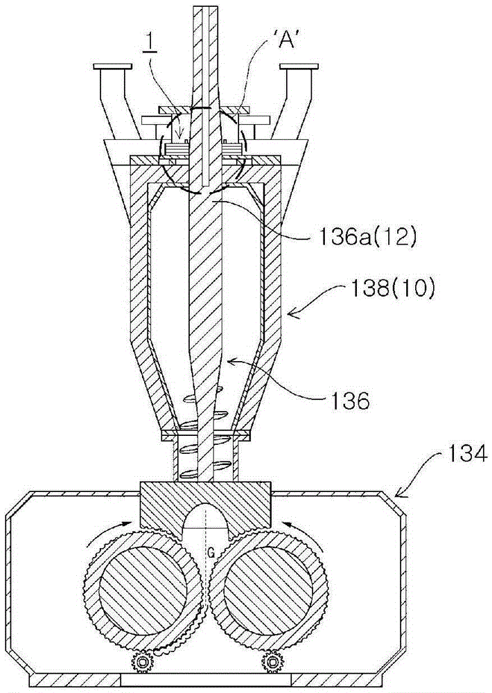
[0044] first, Figure 1 to Figure 3 Schematically shows the molten iron manufacturing equipment 100 using steam coal and fine iron ore, the molten iron manufacturing equipment 100 includes a block manufacturing unit 130, the block manufacturing unit 130 has a driving part sealing device ( image 3 Part 'A') of the screw feeder hopper 138.

[0045] For example, iffigure 1 As shown, the molten iron manufacturing facility 100 that directly uses steam coal and fine iron ore to manufacture molten iron includes a plurality of reduction furnaces 110 , a lump manufacturing unit 130 , a lump storage tank 150 , and a melting furnace 170 . A molten iron manufacturing facility 100 having such a structure is known.

[0046] However, as explained above, in order to ensure the gas permeability in the melting furnace 170, the reduced iron passed through the reduction furnace is manufactur...


PUM


Abstract

A driving portion sealing device for maintaining airtightness at a portion of a driving portion (drive shaft) passing through a closed structure is provided, the driving portion sealing device includes: a structure mounting member mounted on a structure, and passing the driving part; a driving part fixing member provided on the structure mounting member and fixed to the driving part passing through the structure mounting member, thereby sealing the driving part; and , a rotation absorbing portion provided between the driving portion fixing member and the structure mounting member so as to cooperate with each other to absorb rotation. According to the present invention, maintaining the airtightness of structures, especially in hoppers or hoppers with screw feeders, effectively maintains the airtightness of the portion through which the drive shaft of the screw feeder passes, and absorbs the Vibration (vibration), and by absorbing the rotation of the drive shaft and maintaining sealing, wear is suppressed and the sealing effect is maximized.

Description

technical field [0001] The present invention relates to a driving part sealing device for maintaining the airtightness of the driving part (for example, a drive shaft part penetrating a structure (container)), and more specifically, relates to a driving part sealing device in which For example, in a structure (container) such as a hopper or a hopper with a screw feeder, the sealing of the structure part through which the drive part (shaft) of the screw feeder penetrates is effectively maintained, and especially, the absorption of Vibration (vibration), and rotation (force) is absorbed and sealing is provided by the ring structures arranged alternately with each other, wear is suppressed and the effect of sealing is maximized. Background technique [0002] Most of the molten iron produced by steel mills is produced by the blast furnace method in which sintered iron ore and coke made from bituminous coal are charged into a blast furnace and reduced to iron to produce molten ir...

Claims


Application Information

Patent Timeline
Patent Type & Authority Patents(China)
IPC IPC(8): C22B1/16F27B21/08
CPCC21B13/0013C21B13/0046C21B13/0066C21B13/0086C21B13/143F27D3/08F27D99/00F27D99/0073C22B1/16F27B19/00
Inventor 全相镇赵明镐崔承鎬
Owner 浦项控股股份有限公司
Learn More