Electromagnetic actuator

An electromagnetic actuator and magnetic circuit technology, applied in the direction of electromagnetic relays, relays, electromagnets, etc., can solve problems such as difficult to manufacture magnetic pole bodies, complex structures, etc., and achieve the effect of simplified and easy to manufacture

Inactive Publication Date: 2014-08-06
EATON IND NETHERLANDS
View PDF9 Cites 0 Cited by
  • Summary
  • Abstract
  • Description
  • Claims
  • Application Information

AI Technical Summary

Problems solved by technology

[0004] Because the first coil and the second coil are arranged axially behind each other, it is difficult to manufacture the pole body due to this complicated structure

Method used


Image

  • Electromagnetic actuator
  • Electromagnetic actuator

Examples


Embodiment Construction

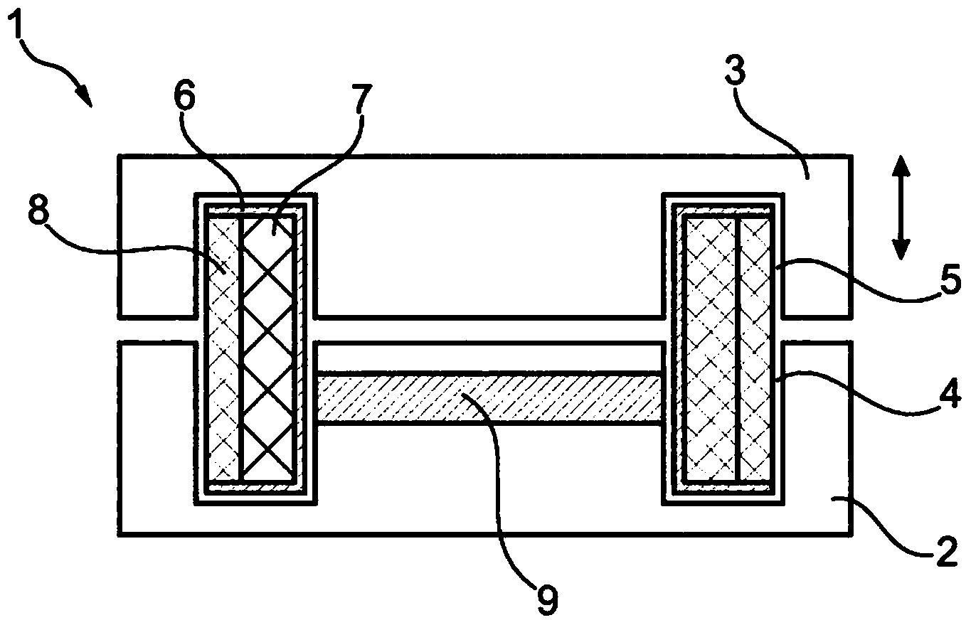
[0027] figure 1 A first embodiment of an actuator 1 according to the invention is shown. The actuator 1 has a fixed pole body 2 and an axially movable pole body 3 . The fixed pole body 2 has concentric recesses 4 and the movable pole body 3 has corresponding concentric recesses 5 .

[0028] The recesses 4 and 5 provide an annular space in which the coil frame 6 is arranged with the first coil 7 and the second coil 8 .

[0029] The permanent magnet 9 is located concentrically in the concentric recess 4 in the fixed pole body 2 .

[0030] In use of the electromagnetic actuator 1 the external spring will urge the pole bodies 2, 3 away from each other. One contact of the switch is connected to the movable pole body so that the switch is opened when the pole bodies 2, 3 are moved away from each other.

[0031] To switch on the switch and to bring the contacts of the switch into contact, power is supplied to the first coil 7 , which forms a first magnetic circuit with the pole b...


PUM


Abstract

The invention relates to an electromagnetic actuator for operating at least one movable contact of a switch into a switched-on position or a switched-off position, wherein the electromagnetic actuator comprises: -a static pole body; -a movable pole body movable relative to the static pole body; -a first magnetic circuit comprising a first coil for making the movable pole body and the fixed pole body move towards each other to a switched-on position and a second coil for making the movable pole body and the fixed pole body move away from each other to a switched-off position; and -a second magnetic circuit comprising a permanent magnet and a retaining plate to keep the static pole body and the movable pole body in the switched-on position; -first spring means for urging the static pole body and the movable body away from each other; wherein the first and second magnetic circuit are arranged concentrically.

Description

technical field [0001] The invention relates to an electromagnetic actuator for operating at least one movable contact of a switch into an on position or an off position. In particular, the invention relates to electromagnetic actuators for medium and high voltage switchgear. These actuators are used to bring together the contacts of the switch or to separate said contacts. Background technique [0002] WO2004100198 describes an electromagnetic actuator for operating a switch. The actuator has a coil for engaging two pole bodies. Permanent magnets are provided to keep the pole bodies in contact even when the coils are not powered. In order to open the contacts in the switch, a second coil is provided which counteracts the magnetic force of the permanent magnet. Springs are provided to urge the pole bodies away from each other. [0003] Both the coil and the permanent magnet are arranged axially behind each other. This results in a relatively long actuator. Also due to...

Claims


Application Information

Patent Timeline
Patent Type & Authority Applications(China)
IPC IPC(8): H01F7/16H01H33/666
CPCH01H36/00H01H51/2209H01H51/22H01H33/6662H01H51/01H01H53/015H01H2036/0086H01F7/1615
Inventor A·拉莫斯
Owner EATON IND NETHERLANDS
Why Eureka
Try Eureka