Method for operating forging hammer

A forging hammer and hammer head technology, applied in the field of running forging hammers, can solve the problems of expensive and costly analog computing technology, and achieve the effects of low cost, optimized cycle time, and no time delay

Active Publication Date: 2014-08-13
SCHULER PRESSEN GMBH & CO KG
View PDF6 Cites 10 Cited by
  • Summary
  • Abstract
  • Description
  • Claims
  • Application Information

AI Technical Summary

Problems solved by technology

The fundamental disadvantages that come with simulations are that simulations are computationally expensive and are performed based on assumptions such that the results of the simulations do not necessarily correspond to the actual results
Especially in the case of a large number of different workpieces, the preparation of the individual simulations represents a huge effort

Method used


Image

  • Method for operating forging hammer
  • Method for operating forging hammer

Examples


Embodiment Construction

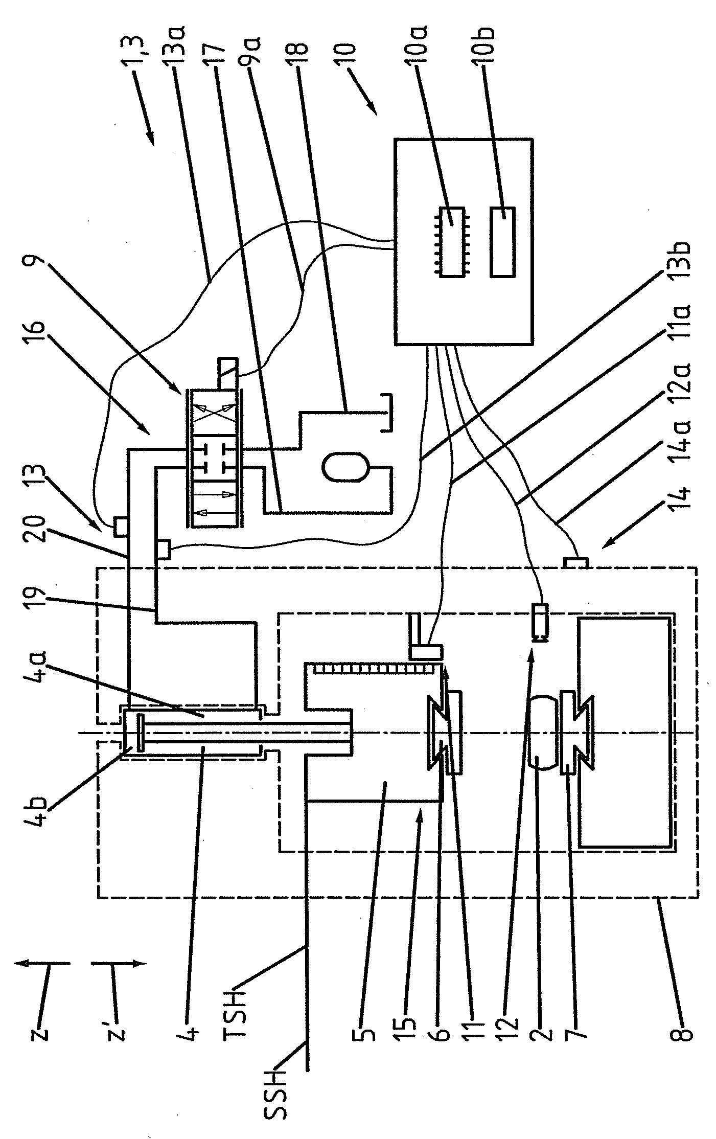
[0023] figure 1 The forging hammer 1 is shown schematically in FIG. The forging hammer 1 is provided for forging a workpiece 2 and is designed as a short-stroke die forging hammer 3 . The forging hammer 1 comprises a hydraulic cylinder 4 , a hammer head 5 , an upper die 6 , a lower die 7 , a machine frame 8 , a control valve 9 , an electronic control device 10 and four sensor devices 11 , 12 , 13 and 14 . The hammer head 5 and the upper die 6 constitute an upper tool 15 moved by the hydraulic cylinder 4 . Furthermore, the forging hammer 1 comprises a hydraulic circuit 16 in which the hydraulic cylinder 4 and the control valve 9 participate. The control valve 9 is connected to the oil inlet port 17 and the oil outlet port 18 and is connected to the double-acting hydraulic cylinder 4 via lines 19 , 20 . The sensor devices 11 to 14 and the control valve 9 are connected to the actuating device 10 via data lines 11a, 12a, 13a, 13b, 14a and 9a. The control device 10 includes a m...


PUM


Abstract

The invention relates to a method for operating a forging hammer (1). The forging hammer (1) comprises a hydraulic cylinder (4), a hammerhead (5), an upper die (6), a lower die (7), a machine frame (8), at least one control valve (9), an electronic control device (10) and at least one sensing device (11-14), wherein the hammerhead (5) and the upper die (6) form an upper tool (15) moved by the hydraulic cylinder (4).

Description

technical field [0001] The invention relates to a method for operating a forging hammer according to the preamble of claim 1 . Background technique [0002] A method for operating a forging hammer is known from DE 10 2006 041 223 A1, in which control and regulation errors are compensated by numerical simulation. The fundamental disadvantage brought about by simulations is that they are computationally expensive and are performed based on assumptions, so that the results of the simulation do not necessarily correspond to the actual results. Especially in the case of a large number of different workpieces, the preparation of the individual simulations involves considerable effort. [0003] In addition, a method for forming at least one workpiece is known from DE 103 32 888 C5, wherein the striking tool starts from a predetermined or predefinable starting position with a predetermined A predetermined or predeterminable impact velocity is used to impact the workpiece on the ca...

Claims


Application Information

Patent Timeline
Patent Type & Authority Applications(China)
IPC IPC(8): B21J5/00B21J9/20B21J9/12
CPCB21J7/46B21J5/00B21J11/00
Inventor A.德雷赫尔M.贝洛赫
Owner SCHULER PRESSEN GMBH & CO KG
Why Eureka
Try Eureka